-
Use the same procedure for the RH and LH sides.
-
The procedure listed below is for the LH side.
-
Click here
INSTALL OUTER REAR VIEW MIRROR ASSEMBLY
-
Attach the claw and Install the mirror with the 3 nuts.
8.0 N*m 82 kgf*cm 71 in.*lbf -
w/ Power Mirror Control System:
-
Attach the clamp.
-
Connect the connector labeled A.
-
-
- Click here
INSTALL FRONT DOOR TRIM BOARD SUB-ASSEMBLY
-
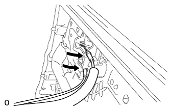
Connect the connector.
-
Connect the front door lock remote control cable assembly LH and front door inside locking cable assembly LH to the front door inside handle sub-assembly LH.
-
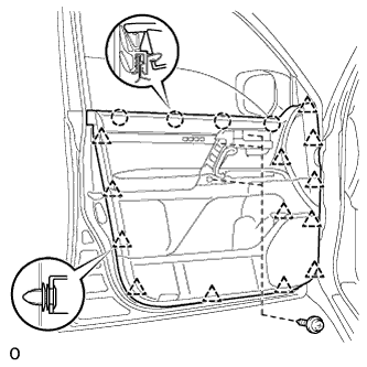
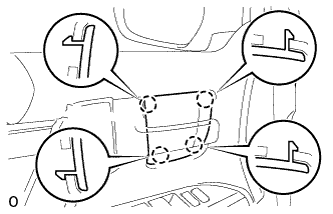
Attach the 4 claws and 13 clips to install the front door trim board sub-assembly LH.
-
Install the 3 screws.
-
- Click here
INSTALL FRONT DOOR LOWER FRAME BRACKET GARNISH
-
Attach the clip and claw, and install the front door lower frame bracket garnish LH.
-
- Click here
INSTALL DOOR ASSIST GRIP COVER
-
Attach the 8 claws to install the door assist grip cover LH to the front door trim board sub-assembly LH.
-
- Click here
INSTALL FRONT UPPER ARMREST BASE PANEL LH
-
Connect the connector.
-

Attach the 5 claws to install the armrest base panel.
-
- Click here
INSTALL FRONT DOOR INSIDE HANDLE BEZEL
-
Attach the 4 claws to install the front door inside handle bezel LH.
-
- Click here
CONNECT CABLE TO NEGATIVE BATTERY TERMINAL
Note:When disconnecting the cable, some systems need to be initialized after the cable is reconnected (Click here).