- Click here
PRECAUTION
Note:After turning the ignition switch off, waiting time may be required before disconnecting the cable from the battery terminal. Therefore, make sure to read the disconnecting the cable from the battery terminal notice before proceeding with work (Click here).
- Click here
DISCONNECT CABLE FROM NEGATIVE BATTERY TERMINAL
Note:When disconnecting the cable, some systems need to be initialized after the cable is reconnected (Click here).
- Click here
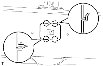
REMOVE BACK DOOR GRIP
-
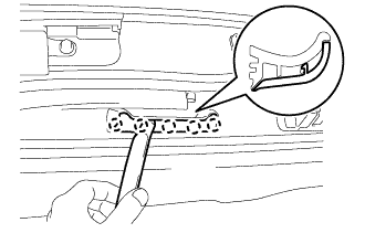
Using a moulding remover, detach the 5 claws and open the cover.
-
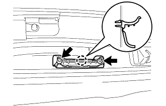
Using a T30 "TORX" wrench, remove the 2 screws.
-
Detach the claw and remove the back door grip.
-
- Click here
REMOVE LOWER BACK DOOR STOPPER CUSHION
-
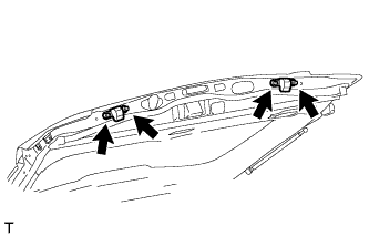
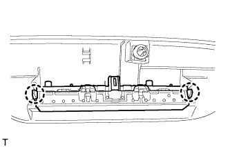
Remove the 4 bolts and 2 lower back door stopper cushions.
-
- Click here
REMOVE CENTER BACK DOOR GARNISH
-
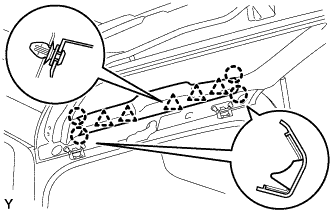
Detach the 5 clips and 4 claws, and remove the center back door garnish.
-
- Click here
REMOVE CENTER STOP LIGHT ASSEMBLY
-
Detach the 2 claws and remove the stop light.
-
- Click here
REMOVE BACK DOOR SIDE GARNISH LH
-
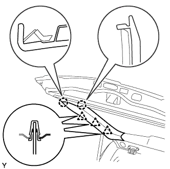
Detach the 3 clips and 2 claws, and remove the back door side garnish LH.
-
- Click here
REMOVE BACK DOOR SIDE GARNISH RH
-
w/o Power Back Door:
Tip:Use the same procedure described for the LH side.
-
w/ Power Back Door:
-
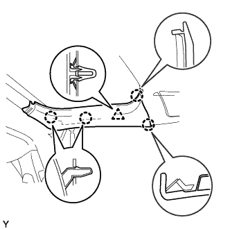
Detach the clip and 4 claws, and remove the back door side garnish RH.
-
-
- Click here
REMOVE BACK DOOR SERVICE HOLE COVER RH (w/ Power Back Door)
-

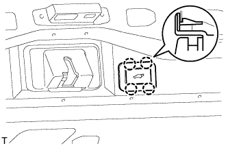
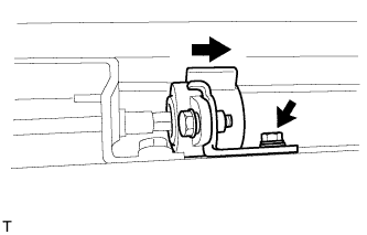
Move the back door to a half-open position so that the hole in the center of the back door service hole cover RH is aligned lengthwise with the power back door rod.
Table 1. Text in Illustration *1 Power Back Door Rod *2 Hole of Back Door Service Hole Cover RH *a Back Door is Half-open -

Detach the 2 clips and separate the back door service hole cover RH, passing the power back door rod through the hole of the back door service hole cover RH.
Note:If the back door is in a fully-open position, the power back door rod will interfere with the hole of the back door service hole cover RH, so do not perform this operation with the back door in a fully open position.
Tip:If any of the clips have remained on the back door, remove the clips from the back door and install them to the back door service hole cover RH.
-

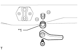
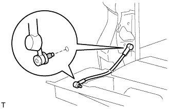
Remove the ball joint bolt, power back door rod and back door stay plate.
-
Remove the back door service hole cover RH from the power back door rod.
-
- Click here
REMOVE ASSIST GRIP (for Face to Face Seat Type)
-
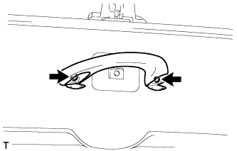
Remove the 2 screws and assist grip.
-
- Click here
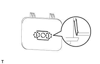
REMOVE NO. 2 BACK DOOR SERVICE HOLE COVER (for Face to Face Seat Type)
-
Using a screwdriver, detach the 4 claws and remove the No. 2 back door service hole cover.
-
Disconnect connector.
-
- Click here
REMOVE DOOR OPENING SWITCH SUB-ASSEMBLY (for Face to Face Seat Type)
-
Detach the 2 claws and remove the door opening switch sub-assembly.
-
- Click here
REMOVE BACK DOOR GARNISH
-
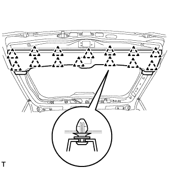
Using a screwdriver, detach the 14 clips and remove the back door garnish.
Tip:Tape the screwdriver tip before use.
-
- Click here
REMOVE REAR HEADER SPEAKER ASSEMBLY (for 14 Speakers)
Tip:Use the same procedure as for the opposite side.
-
Remove the 3 screws.
-
Disconnect the connector and remove the rear header speaker assembly.
-
- Click here
REMOVE REAR ASSIST GRIP REINFORCEMENT (for Face to Face Seat Type)
-
Remove the 3 bolts.
-
Detach the 2 claws and remove the rear assist grip reinforcement.
-
- Click here
REMOVE POWER BACK DOOR SENSOR ASSEMBLY LH (w/ Power Back Door)
-
Disconnect the connector.
-
Using a T25 "TORX" wrench, remove the 6 screws.
-
Detach the 2 clips and remove the power back door sensor assembly LH.
-
- Click here
REMOVE POWER BACK DOOR SENSOR ASSEMBLY RH (w/ Power Back Door)
Tip:Use the same procedure described for the LH side.
- Click here
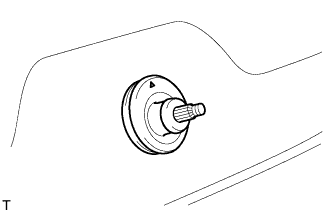
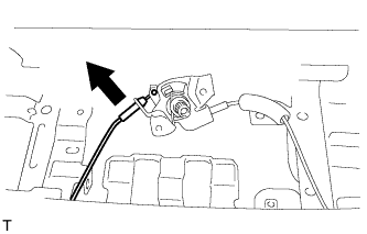
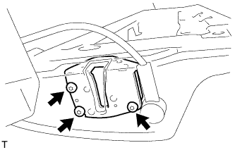
REMOVE REAR WIPER ARM (w/ Rear Wiper)
-
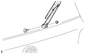
Open the cover.
-
Remove the nut and rear wiper arm.
-
- Click here
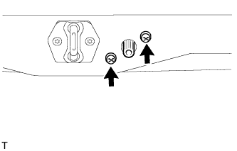
REMOVE REAR WIPER MOTOR GROMMET (w/ Rear Wiper)
-
Detach the rear wiper motor grommet.
-
- Click here
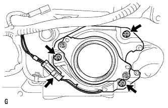
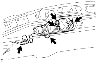
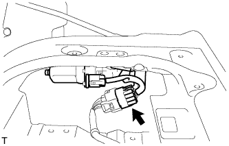
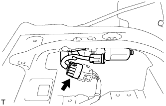
REMOVE REAR WIPER MOTOR ASSEMBLY (w/ Rear Wiper)
-
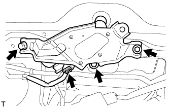
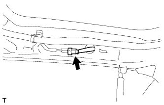
Disconnect the connector.
-
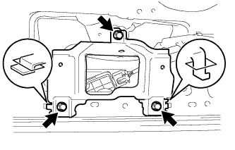
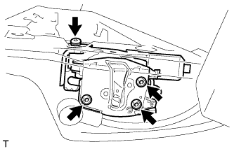
Remove the 3 bolts and rear wiper motor assembly.
-
- Click here
REMOVE BACK DOOR LOCK COVER
-
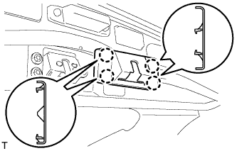
Detach the 4 claws and remove the back door lock cover.
-
- Click here
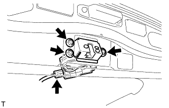
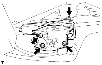
REMOVE BACK DOOR LOCK ASSEMBLY
-
w/o Power Back Door:
-
Disconnect the connector.
-
Remove the 3 bolts and back door lock assembly.
-
-
w/ Power Back Door:
-
Disconnect the connector.
-
Detach the guide.
-
Remove the 4 bolts and back door lock assembly.
-
-
- Click here
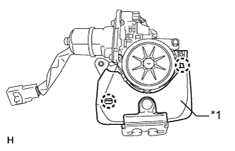
REMOVE BACK DOOR LOCK PROTECTOR (w/ Power Back Door)
-
Remove the screw.
-
Detach the 7 claws, and remove the protector (B).
Table 2. Text in Illustration *1 Protector (B) -
Detach the 2 claws, and remove the protector (A).
Table 3. Text in Illustration *1 Protector (A)
-
- Click here
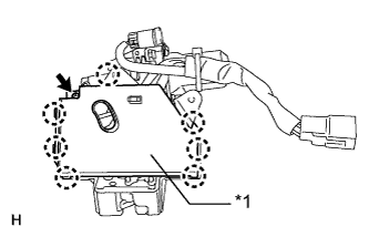
REMOVE BACK DOOR CONTROL SWITCH (w/ Power Back Door)
-
Disconnect the connector.
-
Detach the 4 claws and remove the back door control switch.
-
- Click here
REMOVE LICENSE PLATE LIGHT LENS (for Standard)
-
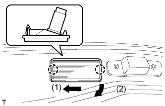
Detach the 2 claws in the order shown in the illustration and remove the license plate light.
-
Disconnect the connector.
-
- Click here
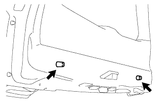
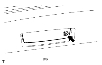
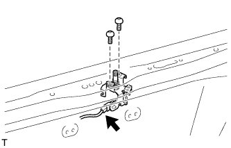
REMOVE BACK DOOR OPENER SWITCH ASSEMBLY
-
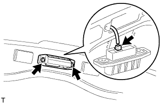
Remove the 2 screws.
-
Disconnect the connector and then remove the back door opener switch assembly.
-
-
Click here
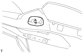
REMOVE REAR TELEVISION CAMERA ASSEMBLY (w/ Parking Assist Monitor System or Rear View Monitor System)
-
Using a T30 "TORX" socket wrench, remove the 2 screws.
-
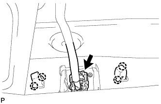
Detach the 4 claws and remove the rear television camera assembly.
-
Disconnect the connector.
-
- Click here
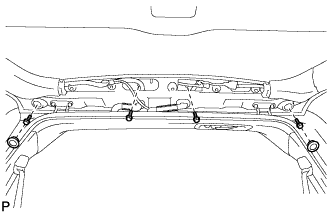
REMOVE LIFT GATE WEATHERSTRIP
-
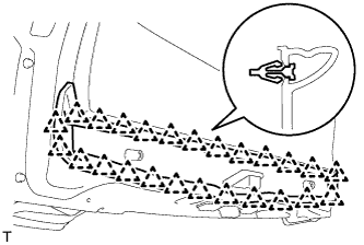
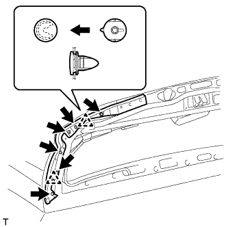
Detach the 25 clips and remove the lift gate weatherstrip.
Note:Do not pull strongly on the lift gate weatherstrip as it may tear.
-
- Click here
REMOVE CUSHION
-
Remove the 2 cushions.
-
- Click here
REMOVE LOWER BACK DOOR STOPPER
-
Remove the bolt and lower back door stopper.
-
- Click here
REMOVE BACK DOOR OUTSIDE GARNISH SUB-ASSEMBLY
-
Put protective tape around the back door garnish.
-
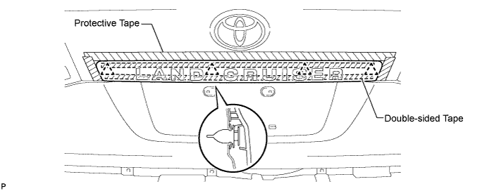
Detach the 4 clips and remove the double-sided tape to remove the back door garnish.
-
-
Click here
REMOVE BACK DOOR GLASS CHANNEL LH (w/o Power Back Door)
-
Using a clip remover, remove the clip.
-
Remove the back door glass channel LH.
-
- Click here
REMOVE BACK DOOR GLASS CHANNEL RH (w/o Power Back Door)
Tip:Use the same procedure described for the LH side.
- Click here
REMOVE REAR SPOILER SUB-ASSEMBLY (w/ Rear Spoiler)
-
w/ Power Back Door:
-
Remove the 2 hole plugs and 4 bolts.
-
-
w/o Power Back Door:
Remove the 4 bolts.
-
Detach the 3 clips and remove the rear spoiler sub-assembly.
-
- Click here
REMOVE REAR WASHER NOZZLE (w/ Rear Wiper)
-
Disconnect the washer hose.
-
Detach the 2 claws and remove the rear washer nozzle.
-
- Click here
REMOVE BACK DOOR STAY ASSEMBLY LH
-
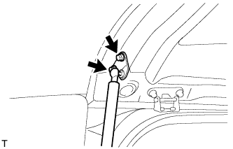
Remove the 2 bolts and stay.
CAUTION:Remove the door stay while supporting the back door with one hand.
-
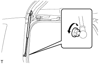
Remove the bolt and stay.
CAUTION:Remove the door stay while supporting the back door with one hand.
-
- Click here
REMOVE BACK DOOR STAY ASSEMBLY RH
Tip:Use the same procedure described for the LH side.
-
Click here
REMOVE REAR FLOOR MAT REAR SUPPORT PLATE
-
Detach the 6 clips and remove the support plate.
-
- Click here
REMOVE BACK DOOR TRIM COVER LH
-
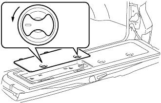
Remove the back door trim cover LH as shown in the illustration.
-
- Click here
REMOVE BACK DOOR TRIM COVER RH
-
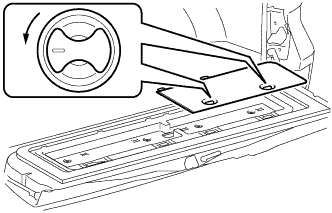
Remove the back door trim cover RH as shown in the illustration.
-
- Click here
REMOVE BACK DOOR TRIM PANEL ASSEMBLY
-
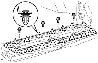
Remove the 4 bolts.
-
Detach the 16 clips and remove the back door trim panel assembly.
-
-
Click here
REMOVE NO. 2 BACK DOOR OUTSIDE GARNISH SUB-ASSEMBLY (w/ Tire Carrier)
-
Remove the 2 nuts and disconnect the connector.
-
Put protective tape around the No. 2 back door garnish.
-
Detach the 8 clips.
-
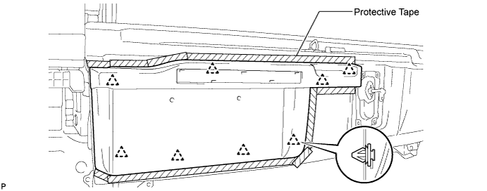
Pull out the wire harness of the license plate light from the tail gate, and remove the No. 2 back door garnish.
-
- Click here
REMOVE LICENSE PLATE LIGHT ASSEMBLY (w/ Tire Carrier)
-
Remove the 2 screws and 2 lights.
-
-
Click here
REMOVE REAR LICENSE LIGHT COVER (w/ Tire Carrier)
-
Put protective tape around the rear license light cover.
-
Detach the 7 claws and remove the double-sided tape to remove the rear license light cover.
-
- Click here
REMOVE REAR BUMPER ASSEMBLY
-
for Standard:
-
Remove the rear bumper assembly (Click here).
-
-
w/ Towing Hitch:
-
Remove the rear bumper assembly (Click here).
-
-
w/ Pintle Hook:
-
Remove the rear bumper assembly (Click here).
-
-
- Click here
REMOVE SPARE TIRE
- Click here
REMOVE LOWER BACK DOOR TORSION BAR ASSEMBLY
-
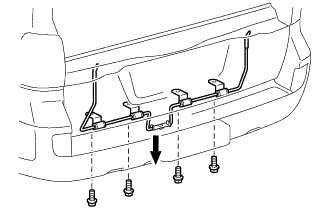
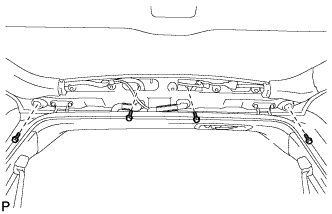
Remove the 4 bolts and lower back door torsion bar assembly.
-
- Click here
REMOVE BACK DOOR TORSION BAR GUIDE
-
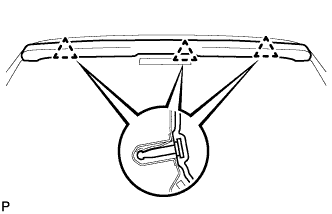
Detach the 2 claws and remove the back door torsion bar guide.
-
- Click here
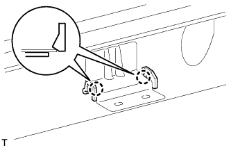
REMOVE BACK DOOR INSIDE HANDLE ASSEMBLY
-
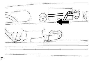
Remove the screw and back door inside handle.
Table 4. Text in Illustration *1 Back Door Handle Grommet -
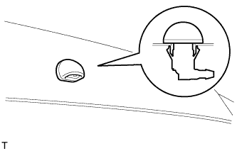
Remove the back door handle grommet.
-
- Click here
REMOVE LOWER TAIL GATE LOCK ASSEMBLY RH
-
w/o Power Back Door:
-
Using a T30 "TORX" wrench, remove the 3 screws and lower tail gate lock assembly RH.
-
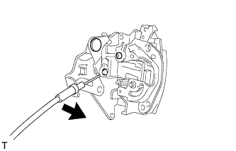
Disconnect the cable from the lower tail gate lock assembly RH.
-
-
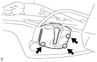
w/ Power Back Door:
-
Disconnect the connector.
-
Using a T30 "TORX" wrench, remove the 4 screws and lower tail gate lock assembly RH.
-
-
- Click here
REMOVE BACK DOOR REMOTE CONTROL ASSEMBLY
-
w/o Power Back Door:
-
Remove the 2 screws.
-
Disconnect the left side cable.
-
Remove the back door remote control assembly.
-
-
w/ Power Back Door:
-
Disconnect the connector.
-
Remove the 2 screws and back door remote control assembly.
-
-
- Click here
REMOVE LOWER TAIL GATE LOCK ASSEMBLY LH
-
w/o Power Back Door:
-
Using a T30 "TORX" wrench, remove the 3 screws and lower tail gate lock assembly LH.
-
-
w/ Power Back Door:
-
Disconnect the connector.
-
Using a T30 "TORX" wrench, remove the 4 screws and lower tail gate lock assembly LH.
-
-
- Click here
REMOVE TAIL GATE STAY SUB-ASSEMBLY LH
-
Using a T40 "TORX" socket, remove the 2 screws and tail gate stay sub-assembly LH.
-
- Click here
REMOVE TAIL GATE STAY SUB-ASSEMBLY RH
Tip:Use the same procedure described for the LH side.
- Click here
REMOVE BACK DOOR DAMPER ASSEMBLY (w/ Power Back Door)
-
Remove the bolt and back door damper assembly.
-