POWER BACK DOOR SYSTEM Back Door Lock Motor Circuit
DESCRIPTION
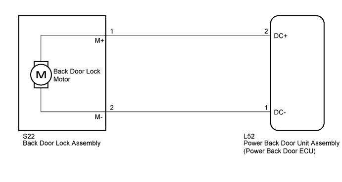
The back door lock motor is built into the back door lock assembly. The power back door unit assembly (power back door ECU) controls the back door lock motor to open/close the back door. This power back door unit assembly (power back door ECU) applies current to terminals 2 and 1 to operate the motor to close the door. It reverses the direction of the current to operate the motor to open the door.
WIRING DIAGRAM
INSPECTION PROCEDURE
PROCEDURE
-
INSPECT BACK DOOR LOCK ASSEMBLY (CLOSER MOTOR OPERATION)
-
Remove the back door lock assembly Click here.
-
Inspect the back door lock assembly Click here.
NG 
REPLACE BACK DOOR LOCK ASSEMBLY Click here
OK 
-
-
CHECK HARNESS AND CONNECTOR (BACK DOOR LOCK ASSEMBLY - POWER BACK DOOR UNIT ASSEMBLY [POWER BACK DOOR ECU])
-
Disconnect the S22 back door lock assembly connector.
-
Disconnect the L52 power back door unit assembly (power back door ECU) connector.
-
Measure the resistance according to the value(s) in the table below.
Standard Resistance Tester Connection Condition Specified Condition S22-1 (M+) - L52-2 (DC+) Always Below 1 Ω S22-2 (M-) - L52-1 (DC-) Always Below 1 Ω S22-1 (M+) - Body ground Always 10 kΩ or higher S22-2 (M-) - Body ground Always 10 kΩ or higher
NG
REPAIR OR REPLACE HARNESS OR CONNECTOR
OK 
PROCEED TO NEXT SUSPECTED AREA SHOWN IN PROBLEM SYMPTOMS TABLE Click here
-