TAIL GATE CLOSER SYSTEM Tail Gate Closer does not Operate
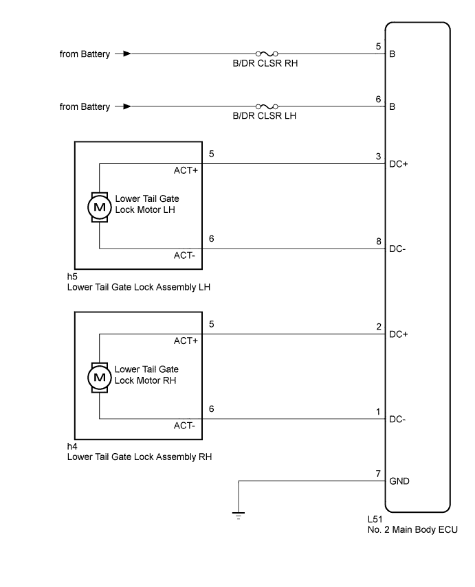
WIRING DIAGRAM
INSPECTION PROCEDURE
Note
Inspect the fuses for circuits related to this system before performing the following inspection procedure.
PROCEDURE
-
CHECK HARNESS AND CONNECTOR (NO. 2 MAIN BODY ECU - BATTERY AND BODY GROUND)
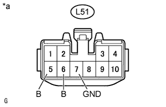
Text in Illustration *a Front view of wire harness connector
(to No. 2 Main Body ECU)
-
Disconnect the No. 2 main body ECU connector.
-
Measure the voltage according to the value(s) in the table below.
Standard Voltage Tester Connection Condition Specified Condition L51-5 (B) - Body ground Always 11 to 14 V L51-6 (B) - Body ground Always 11 to 14 V -
Measure the resistance according to the value(s) in the table below.
Standard Resistance Tester Connection Condition Specified Condition L51-7 (GND) - Body ground Always Below 1 Ω
NG 
REPAIR OR REPLACE HARNESS OR CONNECTOR
OK 
-
-
INSPECT LOWER TAIL GATE LOCK ASSEMBLY
-
for LH:
-
Remove the lower tail gate lock assembly LH Click here.
-
Inspect the lower tail gate lock assembly LH Click here.
-
-
for RH:
-
Remove the lower tail gate lock assembly RH Click here.
-
Inspect the lower tail gate lock assembly RH Click here.
Result Result Proceed to OK A NG (for LH) B NG (for RH) C -
B
REPLACE LOWER TAIL GATE LOCK ASSEMBLY LH Click here
C
REPLACE LOWER TAIL GATE LOCK ASSEMBLY RH Click here
A
-
-
CHECK HARNESS AND CONNECTOR (LOWER TAIL GATE LOCK ASSEMBLY - NO. 2 MAIN BODY ECU)
-
for LH:
-
Disconnect the h5 lower tail gate lock assembly LH connector.
-
Disconnect the L51 No. 2 main body ECU connector.
-
Measure the resistance according to the value(s) in the table below.
Standard Resistance Tester Connection Condition Specified Condition h5-5 (ACT+) - L51-3 (DC+) Always Below 1 Ω h5-6 (ACT-) - L51-8 (DC-) Always Below 1 Ω h5-5 (ACT+) - Body ground Always 10 kΩ or higher h5-6 (ACT-) - Body ground Always 10 kΩ or higher
-
-
for RH:
-
Disconnect the h4 lower tail gate lock assembly RH connector.
-
Disconnect the L51 No. 2 main body ECU connector.
-
Measure the resistance according to the value(s) in the table below.
Standard Resistance Tester Connection Condition Specified Condition h4-5 (ACT+) - L51-2 (DC+) Always Below 1 Ω h4-6 (ACT-) - L51-1 (DC-) Always Below 1 Ω h4-5 (ACT+) - Body ground Always 10 kΩ or higher h4-6 (ACT-) - Body ground Always 10 kΩ or higher
-
NG
REPAIR OR REPLACE HARNESS OR CONNECTOR
OK 
REPLACE NO. 2 MAIN BODY ECU Click here
-