WINDOW DEFOGGER SYSTEM (for Double Swing Out Type) TERMINALS OF ECU

-
CHECK AIR CONDITIONING AMPLIFIER ASSEMBLY
-
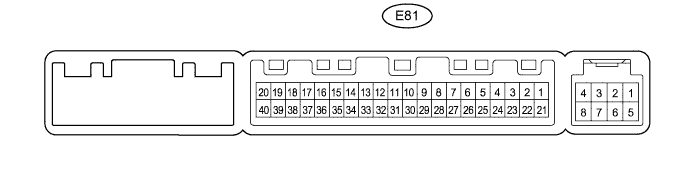
Disconnect the E81 air conditioning amplifier assembly connector.
-
Measure the resistance and voltage according to the value(s) in the table below.
Terminal No. (Symbol) Wiring Color Terminal Description Condition Specified Condition E81-1 (IG+) - E81-14 (GND) G - W-B Ignition power supply Ignition switch ON 11 to 14 V Ignition switch off Below 1 V E81-21 (+B1) - E81-14 (GND) R - W-B Battery power source Always 11 to 14 V E81-14 (GND) - Body ground W-B - Body ground Ground Always Below 1 Ω
-
If the result is not as specified, there may be a malfunction on the wire harness side.
-
-
Reconnect the E81 air conditioning amplifier assembly connector.
-
Measure the voltage according to the value(s) in the table below.
Terminal No. (Symbol) Wiring Color Terminal Description Condition Specified Condition E81-38 (RDEF) - E81-14 (GND) G - W-B Defogger relay Ignition switch ON and defogger switch off 11 to 14 V Ignition switch ON and defogger switch on Below 1 V
-
If the result is not as specified, the air conditioning amplifier assembly or fuse may have a malfunction.
-
-
-
CHECK AIR CONDITIONING CONTROL ASSEMBLY
-
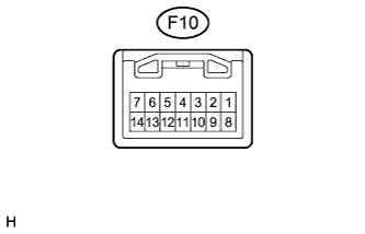
Disconnect the F10 air conditioning control assembly connector.
-
Measure the resistance and voltage according to the value(s) in the table below.
Terminal No. (Symbol) Wiring Color Terminal Description Condition Specified Condition F10-7 (IG+) - F10-1 (GND) G - W-B Ignition power supply Ignition switch ON 11 to 14 V Ignition switch off Below 1 V F10-1 (GND) - Body ground W-B - Body ground Ground Always Below 1 Ω
-
If the result is not as specified, there may be a malfunction on the wire harness side.
-
-