POWER WINDOW CONTROL SYSTEM (for Models with Jam Protection Function on Driver Door Window Only) Front Passenger Side Power Window does not Operate with Front Passenger Side Power Window Switch
DESCRIPTION
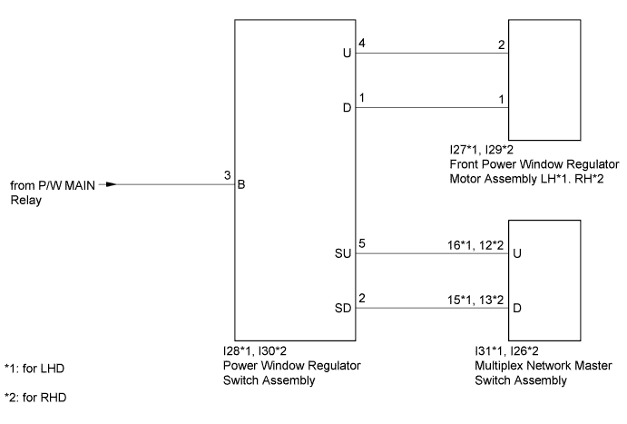
If the manual up/down function does not operate, there may be a malfunction in the power window regulator switch assembly, front power window regulator motor assembly LH*1 or RH*2, multiplex network master switch assembly or harness or connector.
-
*1: for LHD
-
*2: for RHD
WIRING DIAGRAM
INSPECTION PROCEDURE
PROCEDURE
-
INSPECT POWER WINDOW REGULATOR SWITCH ASSEMBLY
-
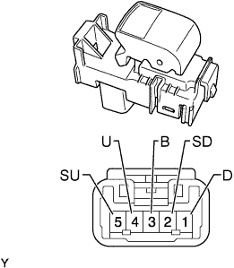
Remove the power window regulator switch assembly Click here.
-
Measure the resistance according to the value(s) in the table below.
Standard Resistance Tester Connection Switch Condition Specified Condition 4 (U) - 3 (B) UP Below 1 Ω 2 (SD) - 1 (D) 5 (SU) - 4 (U) OFF Below 1 Ω 2 (SD) - 1 (D) 5 (SU) - 4 (U) DOWN Below 1 Ω 3 (B) - 1 (D)
NG 
REPLACE POWER WINDOW REGULATOR SWITCH ASSEMBLY Click here
OK 
-
-
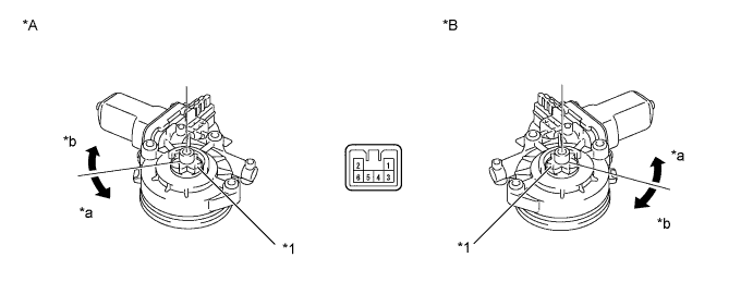
INSPECT FRONT POWER WINDOW REGULATOR MOTOR ASSEMBLY
-
Remove the front passenger side power window regulator motor assembly Click here.
-
Apply battery voltage to the motor connector according to the table below.
Text in Illustration *A for LHD *B for RHD *1 Motor Gear - - *a Counterclockwise *b Clockwise OK Measurement Condition Specified Condition Battery positive (+) → 1
Battery negative (-) → 2
Motor gear rotates clockwise Battery positive (+) → 2
Battery negative (-) → 1
Motor gear rotates counterclockwise Result Result Proceed to OK A NG (for LHD) B NG (for RHD) C
B
REPLACE FRONT POWER WINDOW REGULATOR MOTOR ASSEMBLY RH Click here
C
REPLACE FRONT POWER WINDOW REGULATOR MOTOR ASSEMBLY LH Click here
A
-
-
CHECK HARNESS AND CONNECTOR (POWER WINDOW REGULATOR SWITCH - BATTERY)
-
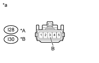
Text in Illustration *A for LHD *B for RHD *a Front view of wire harness connector
(to Power Window Regulator Switch Assembly)
Disconnect the I28*1 or I30*2 power window regulator switch assembly connector.
-
*1: for LHD
-
*2: for RHD
-
-
Measure the voltage according to the value(s) in the table below.
Standard Voltage for LHD Tester Connection Switch Condition Specified Condition I28-3 (B) - Body ground Ignition switch ON 11 to 14 V for RHD Tester Connection Switch Condition Specified Condition I30-3 (B) - Body ground Ignition switch ON 11 to 14 V
NG
REPAIR OR REPLACE HARNESS OR CONNECTOR
OK
-
-
CHECK HARNESS AND CONNECTOR (POWER WINDOW REGULATOR SWITCH - FRONT POWER WINDOW REGULATOR MOTOR)
-
*1: for LHD
-
*2: for RHD
-
Disconnect the I28*1 or I30*2 power window regulator motor assembly connector.
-
Disconnect the I27*1 or I29*2 front power window regulator motor assembly connector.
-
Measure the resistance according to the value(s) in the table below.
Standard Resistance for LHD Tester Connection Condition Specified Condition I28-4 (U) - I27-2 Always Below 1 Ω I28-1 (D) - I27-1 Always Below 1 Ω I28-4 (U) or I27-2 - Body ground Always 10 KΩ or higher I28-1 (D) or I27-1 - Body ground Always 10 KΩ or higher for RHD Tester Connection Condition Specified Condition I30-4 (U) - I29-2 Always Below 1 Ω I30-1 (D) - I29-1 Always Below 1 Ω I30-4 (U) or I29-2 - Body ground Always 10 KΩ or higher I30-1 (D) or I29-1 - Body ground Always 10 KΩ or higher
NG
REPAIR OR REPLACE HARNESS OR CONNECTOR
OK
-
-
CHECK HARNESS AND CONNECTOR (POWER WINDOW REGULATOR SWITCH - MULTIPLEX NETWORK MASTER SWITCH)
-
*1: for LHD
-
*2: for RHD
-
Disconnect the I28*1 or I30*2 power window regulator switch assembly connector.
-
Disconnect the I31*1 or I26*2 multiplex network master switch assembly connector.
-
Measure the resistance according to the value(s) in the table below.
Standard Resistance for LHD Tester Connection Condition Specified Condition I28-5 (SU) - I31-16 (U) Always Below 1 Ω I28-2 (SD) - I31-15 (D) Always Below 1 Ω I28-5 (SU) or I30-16 (U) - Body ground Always 10 kΩ or higher I28-2 (SD) or I30-15 (D) - Body ground Always 10 kΩ or higher for RHD Tester Connection Condition Specified Condition I30-5 (SU) - I26-12 (U) Always Below 1 Ω I30-2 (SD) - I26-13 (D) Always Below 1 Ω I30-5 (SU) or I26-12 (U) - Body ground Always 10 kΩ or higher I30-2 (SD) or I26-13 (D) - Body ground Always 10 kΩ or higher
NG
REPAIR OR REPLACE HARNESS OR CONNECTOR
OK 
REPLACE MULTIPLEX NETWORK MASTER SWITCH ASSEMBLY Click here
-