POWER WINDOW CONTROL SYSTEM (for Models with Jam Protection Function on Driver Door Window Only) Remote Up / Down Function does not Operate
DESCRIPTION
When the ignition switch is ON and window lock switch is off, the multiplex network master switch sends remote up/down signals to each power window regulator motor.
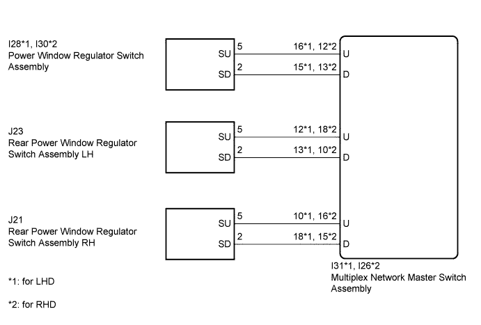
WIRING DIAGRAM
INSPECTION PROCEDURE
PROCEDURE
-
CHECK MULTIPLEX NETWORK MASTER SWITCH ASSEMBLY (WINDOW LOCK SWITCH)
-
Turn the window lock switch off and operate the switches on the multiplex network master switch. Check that the remote up/down function operates Click here.
OK Remote up/down function operates.
NG 
CHECK MANUAL UP / DOWN FUNCTION Click here
OK 
END
-
-
CHECK MANUAL UP / DOWN FUNCTION
-
Check that the front passenger side power window and rear power window manual up/down function operates normally.
OK Manual up/down function operates normally.
NG 
PROCEED TO NEXT SUSPECTED AREA SHOWN IN PROBLEM SYMPTOMS TABLE Click here
OK 
-
-
CHECK HARNESS AND CONNECTOR (MULTIPLEX NETWORK MASTER SWITCH - POWER WINDOW REGULATOR SWITCH)
-
*1: for LHD
-
*2: for RHD
-
Disconnect the I31*1 or I26*2 multiplex network master switch assembly connector.
-
Disconnect the I28*1 or I30*2 power window regulator switch assembly connector.
-
Measure the resistance according to the value(s) in the table below.
Standard Resistance for LHD Tester Connection Condition Specified Condition I31-16 (U) - I28-5 (SU) Always Below 1 Ω I31-15 (D) - I28-2 (SD) Always Below 1 Ω I31-16 (U) or I28-5 (SU) - Body ground Always 10 kΩ or higher I31-15 (D) or I28-2 (SD) - Body ground Always 10 kΩ or higher for RHD Tester Connection Condition Specified Condition I26-12 (U) - I30-5 (SU) Always Below 1 Ω I26-13 (D) - I30-2 (SD) Always Below 1 Ω I26-12 (U) or I30-5 (SU) - Body ground Always 10 kΩ or higher I26-13 (D) or I30-2 (SD) - Body ground Always 10 kΩ or higher
NG
REPAIR OR REPLACE HARNESS OR CONNECTOR
OK
-
-
CHECK HARNESS AND CONNECTOR (MULTIPLEX NETWORK MASTER SWITCH - REAR POWER WINDOW REGULATOR SWITCH LH)
-
Disconnect the I31*1 or I26*2 multiplex network master switch assembly connector.
-
*1: for LHD
-
*2: for RHD
-
-
Disconnect the J23 rear power window regulator switch assembly LH connector.
-
Measure the resistance according to the value(s) in the table below.
Standard Resistance for LHD Tester Connection Condition Specified Condition I31-12 (U) - J23-5 (SU) Always Below 1 Ω I31-13 (D) - J23-2 (SD) Always Below 1 Ω I31-12 (U) or J23-5 (SU) - Body ground Always 10 kΩ or higher I31-13 (D) or J23-2 (SD) - Body ground Always 10 kΩ or higher for RHD Tester Connection Condition Specified Condition I26-18 (U) - J23-5 (SU) Always Below 1 Ω I26-10 (D) - J23-2 (SD) Always Below 1 Ω I26-18 (U) or J23-5 (SU) - Body ground Always 10 kΩ or higher I26-10 (D) or J23-2 (SD) - Body ground Always 10 kΩ or higher
NG
REPAIR OR REPLACE HARNESS OR CONNECTOR
OK
-
-
CHECK HARNESS AND CONNECTOR (MULTIPLEX NETWORK MASTER SWITCH - REAR POWER WINDOW REGULATOR SWITCH RH)
-
Disconnect the I31*1 or I26*2 multiplex network master switch assembly connector.
-
*1: for LHD
-
*2: for RHD
-
-
Disconnect the J21 rear power window regulator switch assembly RH connector.
-
Measure the resistance according to the value(s) in the table below.
Standard Resistance for LHD Tester Connection Condition Specified Condition I31-10 (U) - J21-5 (SU) Always Below 1 Ω I31-18 (D) - J21-2 (SD) Always Below 1 Ω I31-10 (U) or J21-5 (SU) - Body ground Always 10 kΩ or higher I31-18 (D) or J21-2 (SD) - Body ground Always 10 kΩ or higher for RHD Tester Connection Condition Specified Condition I26-16 (U) - J21-5 (SU) Always Below 1 Ω I26-15 (D) - J21-2 (SD) Always Below 1 Ω I26-16 (U) or J21-5 (SU) - Body ground Always 10 kΩ or higher I26-15 (D) or J21-2 (SD) - Body ground Always 10 kΩ or higher
NG
REPAIR OR REPLACE HARNESS OR CONNECTOR
OK
REPLACE MULTIPLEX NETWORK MASTER SWITCH ASSEMBLY Click here
-