Click here
-
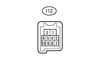
CHECK FRONT POWER WINDOW REGULATOR MOTOR ASSEMBLY LH (for LHD)
-
Disconnect the I12 front power window regulator motor assembly LH connector.
-
Measure the resistance and voltage according to the value(s) in the table below.
Terminal No. (Symbol) Wiring Color Terminal Description Condition Specified Condition I12-2 (B) - I12-1 (GND) L - W-B Battery power supply Always 11 to 14 V I12-1 (GND) - Body ground W-B - Body ground Ground Always Below 1 Ω If the result is not as specified, there may be a malfunction on the wire harness side.
-
Reconnect the I12 front power window regulator motor assembly LH connector.
-
Measure the voltage according to the value(s) in the table below.
Terminal No. (Symbol) Wiring Color Terminal Description Condition Specified Condition I12-10 (UP) - I12-1 (GND) L - W-B Power window up operation Ignition switch ON, multiplex network master switch off → up 11 to 14 V → Below 1 V I12-10 (UP) - I12-1 (GND) L - W-B Power window up operation Ignition switch ON, door glass fully open → power window auto up operation → door glass fully closed 11 to 14 V → Below 1 V → 11 to 14 V I12-7 (DOWN) - I12-1 (GND) B - W-B Power window down operation Ignition switch ON, multiplex network master switch off → down 11 to 14 V → Below 1 V I12-7 (DOWN) - I12-1 (GND) B - W-B Power window down operation Ignition switch ON, door glass fully closed → power window auto down operation → door glass fully open 11 to 14 V → Below 1 V → 11 to 14 V If the result is not as specified, the front power window regulator motor assembly LH may be malfunctioning.
-
-
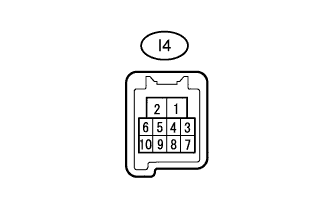
CHECK FRONT POWER WINDOW REGULATOR MOTOR RH (for RHD)
-
Disconnect the I4 front power window regulator motor assembly RH connector.
-
Measure the resistance and voltage according to the value(s) in the table below.
Terminal No. (Symbol) Wiring Color Terminal Description Condition Specified Condition I4-2 (B) - I4-1 (GND) L - W-B Battery power supply Always 11 to 14 V I4-1 (GND) - Body ground W-B - Body ground Ground Always Below 1 Ω If the result is not as specified, there may be a malfunction on the wire harness side.
-
Reconnect the I4 front power window regulator motor assembly RH connector.
-
Measure the voltage according to the value(s) in the table below.
Terminal No. (Symbol) Wiring Color Terminal Description Condition Specified Condition I4-10 (UP) - I4-1 (GND) L - W-B Power window up operation Ignition switch ON, power window regulator switch off → up 11 to 14 V → Below 1 V I4-10 (UP) - I4-1 (GND) L - W-B Power window up operation Ignition switch ON, door glass fully open → power window auto up operation → door glass fully closed 11 to 14 V → Below 1 V → 11 to 14 V I4-7 (DOWN) - I4-1 (GND) B - W-B Power window down operation Ignition switch ON, power window regulator switch off → down 11 to 14 V → Below 1 V I4-7 (DOWN) - I4-1 (GND) B - W-B Power window down operation Ignition switch ON, door glass fully closed → power window auto down operation → door glass fully open 11 to 14 V → Below 1 V → 11 to 14 V If the result is not as specified, the front power window regulator motor assembly may be malfunctioning.
-
-

CHECK MULTIPLEX NETWORK MASTER SWITCH ASSEMBLY
-
*1: for LHD
-
*2: for RHD
-
Disconnect the I31*1 or I26*2 multiplex network master switch assembly connector.
-
Measure the resistance and voltage according to the value(s) in the table below.
Table 1. for LHD Terminal No. (Symbol) Wiring Color Terminal Description Condition Specified Condition I31-6 (B) - I31-1 (E) L - W-B Battery power supply Always 11 to 14 V I31-1 (E) - Body ground W-B - Body ground Ground Always Below 1 Ω Table 2. for RHD Terminal No. (Symbol) Wiring Color Terminal Description Condition Specified Condition I26-6 (B) - I26-9 (E) L - W-B Battery power supply Always 11 to 14 V I26-9 (E) - Body ground W-B - Body ground Ground Always Below 1 Ω If the result is not as specified, there may be a malfunction on the wire harness side.
-
Reconnect the I31*1 or I26*2 multiplex network master switch assembly connector.
-
Measure the voltage according to the value(s) in the table below.
Table 3. for LHD Terminal No. (Symbol) Wiring Color Terminal Description Condition Specified Condition I31-8 (U) - I31-1 (E) L - W-B Power window up operation Ignition switch ON, multiplex network master switch off → up 11 to 14 V → Below 1 V I31-8 (U) - I31-1 (E) L - W-B Power window up operation Ignition switch ON, door glass fully open → power window auto up operation → door glass fully closed 11 to 14 V → Below 1 V → 11 to 14 V I31-5 (D) - I31-1 (E) B - W-B Power window down operation Ignition switch ON, multiplex network master switch off → down 11 to 14 V → Below 1 V I31-5 (D) - I31-1 (E) B - W-B Power window down operation Ignition switch ON, door glass fully closed → power window auto down operation → door glass fully open 11 to 14 V → Below 1 V → 11 to 14 V I31-4 (AUTO) - I31-1 (E) G - W-B Power window up operation Ignition switch ON, door glass fully open → power window auto up operation → door glass fully closed 11 to 14 V → Below 1 V → 11 to 14 V I31-4 (AUTO) - I31-1 (E) G - W-B Power window down operation Ignition switch ON, door glass fully closed → power window auto down operation → door glass fully open 11 to 14 V → Below 1 V → 11 to 14 V I31-3 (LED+) - I31-1 (E) R - W-B LED illumination signal Ignition switch ON 11 to 14 V I31-3 (LED+) - I31-1 (E) R - W-B LED illumination signal Approximately 45 second after ignition switch turned off Below 1 V Table 4. for RHD Terminal No. (Symbol) Wiring Color Terminal Description Condition Specified Condition I26-1 (U) - I26-9 (E) L - W-B Power window up operation Ignition switch ON, multiplex network master switch off → up 11 to 14 V → Below 1 V I26-1 (U) - I26-9 (E) L - W-B Power window up operation Ignition switch ON, door glass fully open → power window auto up operation → door glass fully closed 11 to 14 V → Below 1 V → 11 to 14 V I26-5 (D) - I26-9 (E) B - W-B Power window down operation Ignition switch ON, multiplex network master switch off → down 11 to 14 V → Below 1 V I26-5 (D) - I26-9 (E) B - W-B Power window down operation Ignition switch ON, door glass fully closed → power window auto down operation → door glass fully open 11 to 14 V → Below 1 V → 11 to 14 V I26-4 (AUTO) - I26-9 (E) G - W-B Power window up operation Ignition switch ON, door glass fully open → power window auto up operation → door glass fully closed 11 to 14 V → Below 1 V → 11 to 14 V I26-4 (AUTO) - I26-9 (E) G - W-B Power window down operation Ignition switch ON, door glass fully closed → power window auto down operation → door glass fully open 11 to 14 V → Below 1 V → 11 to 14 V I26-3 (LED+) - I26-9 (E) R - W-B LED illumination signal Ignition switch ON 11 to 14 V I26-3 (LED+) - I26-9 (E) R - W-B LED illumination signal Approximately 45 second after ignition switch turned off Below 1 V If the result is not as specified, the multiplex network master switch assembly may be malfunctioning.
-
-

CHECK FRONT POWER WINDOW REGULATOR SWITCH ASSEMBLY
-
*1: for LHD
-
*2: for RHD
-
Disconnect the I28*1 or I30*2 front power window regulator switch assembly connector.
-
Measure the resistance according to the value(s) in the table below.
Table 5. for LHD Terminal No. (Symbol) Wiring Color Terminal Description Condition Specified Condition I28-3 (B) - Body ground L - Body ground Power supply Ignition switch ON 11 to 14 V I28-5 (SU) - Body ground P - Body ground Ground Always Below 1 Ω I28-2 (SD) - Body ground R-B - Body ground Ground Always Below 1 Ω Table 6. for RHD Terminal No. (Symbol) Wiring Color Terminal Description Condition Specified Condition I30-3 (B) - Body ground L - Body ground Power supply Ignition switch ON 11 to 14 V I30-5 (SU) - Body ground P - Body ground Ground Always Below 1 Ω I30-2 (SD) - Body ground R-B - Body ground Ground Always Below 1 Ω If the result is not as specified, there may be a malfunction on the wire harness side.
-
Reconnect the I28*1 or I30*2 front power window regulator switch assembly connector.
-
Measure the voltage according to the value(s) in the table below.
Table 7. for LHD Terminal No. (Symbol) Wiring Color Terminal Description Condition Specified Condition I28-4 (U) - Body ground L - Body ground Power window up operation Ignition switch ON, power window regulator switch off → up Below 1 V → 11 to 14 V I28-1 (D) - Body ground B - Body ground Power window down operation Ignition switch ON, power window regulator switch off → down Below 1 V → 11 to 14 V Table 8. for RHD Terminal No. (Symbol) Wiring Color Terminal Description Condition Specified Condition I30-4 (U) - Body ground) L - Body ground Power window up operation Ignition switch ON, power window regulator switch off → up Below 1 V → 11 to 14 V I30-1 (D) - Body ground B - Body ground Power window down operation Ignition switch ON, power window regulator switch off → down Below 1 V → 11 to 14 V If the result is not as specified, the front power window regulator switch assembly may be malfunctioning.
-
-

CHECK REAR POWER WINDOW REGULATOR SWITCH ASSEMBLY LH
-
Disconnect the J23 rear power window regulator switch assembly LH connector.
-
Measure the resistance according to the value(s) in the table below.
Terminal No. (Symbol) Wiring Color Terminal Description Condition Specified Condition J23-3 (B) - Body ground L - Body ground Power supply Ignition switch ON 11 to 14 V J23-5 (SU) - Body ground R - Body ground Ground Always Below 1 Ω J23-2 (SD) - Body ground G - Body ground Ground Always Below 1 Ω If the result is not as specified, there may be a malfunction on the wire harness side.
-
Reconnect the J23 rear power window regulator switch assembly LH connector.
-
Measure the voltage according to the value(s) in the table below.
Terminal No. (Symbol) Wiring Color Terminal Description Condition Specified Condition J23-4 (U) - Body ground L - Body ground Power window up operation Ignition switch ON, power window regulator switch off → up Below 1 V → 11 to 14 V J23-1 (D) - Body ground B - Body ground Power window down operation Ignition switch ON, power window regulator switch off → down Below 1 V → 11 to 14 V If the result is not as specified, the rear power window regulator switch assembly LH may be malfunctioning.
-
-
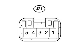
CHECK REAR POWER WINDOW REGULATOR SWITCH ASSEMBLY RH
-
Disconnect the J21 rear power window regulator switch assembly RH connector.
-
Measure the resistance according to the value(s) in the table below.
Terminal No. (Symbol) Wiring Color Terminal Description Condition Specified Condition J21-3 (B) - Body ground L - Body ground Power supply Ignition switch ON 11 to 14 V J21-5 (SU) - Body ground B - Body ground Ground Always Below 1 Ω J21-2 (SD) - Body ground W - Body ground Ground Always Below 1 Ω If the result is not as specified, there may be a malfunction on the wire harness side.
-
Reconnect the J21 rear power window regulator switch assembly RH connector.
-
Measure the voltage according to the value(s) in the table below.
Terminal No. (Symbol) Wiring Color Terminal Description Condition Specified Condition J21-4 (U) - Body ground L - Body ground Power window up operation Ignition switch ON, power window regulator switch off → up Below 1 V → 11 to 14 V J21-1 (D) - Body ground B - Body ground Power window down operation Ignition switch ON, power window regulator switch off → down Below 1 V → 11 to 14 V If the result is not as specified, the rear power window regulator switch assembly RH may be malfunctioning.
-
-
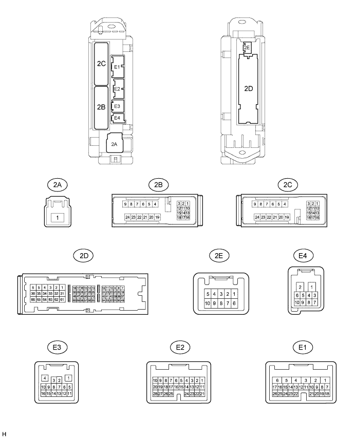
CHECK MAIN BODY ECU (COWL SIDE JUNCTION BLOCK LH)
-
Disconnect the 2A, 2C, 2D, E1 and E2 ECU connectors.
-
Measure the resistance and voltage according to value(s) in the table below.
Terminal No. (Symbol) Wiring Color Terminal Description Condition Specified Condition 2D-62 (GND2) - Body ground W-B - Body ground Ground Always Below 1 Ω 2A-1 (IG) - Body ground B - Body ground IG power supply Always 11 to 14 V E1-24 (DCTY) - Body ground L - Body ground*1
Y - Body ground*2
Driver side door courtesy light switch input Driver side door open Below 1 Ω Driver side door closed 10 kΩ or higher E2-21 (PCTY) - Body ground Y - Body ground*1
L - Body ground*2
Front passenger side door courtesy light switch input Front passenger side door open Below 1 Ω Front passenger side door closed 10 kΩ or higher E1-17 (RCTY) - Body ground G - Body ground Rear RH side door courtesy light switch input Rear RH side door open Below 1 Ω Rear RH side door closed 10 kΩ or higher 2C-2 (LCTY) - Body ground W - Body ground Rear LH side door courtesy light switch input Rear LH side door open Below 1 Ω Rear LH side door closed 10 kΩ or higher
-
*1: for LHD
-
*2: for RHD
-
If the result is not as specified, the wire harness side may have a malfunction.
-
-