POWER WINDOW CONTROL SYSTEM (for Models with Jam Protection Function on 4 Windows) Rear Power Window LH Auto Up / Down Function does not Operate with Rear Power Window Switch LH
DESCRIPTION
-
If the auto up/down function does not operate, the cause may be one or more of the following:
-
The ECU in the power window regulator motor determines that the power window regulator motor has not been initialized.
-
The power window regulator switch has a malfunction.
-
The Hall-IC in the power window regulator motor has a malfunction.
-
There is an open or short in the wiring between the rear power window regulator switch and the power window regulator motor.
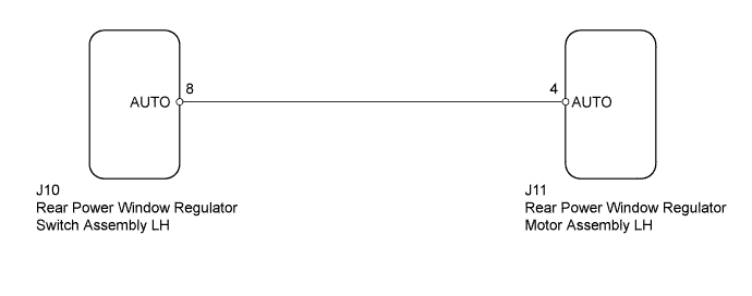
WIRING DIAGRAM
INSPECTION PROCEDURE
PROCEDURE
-
CHECK FOR DTC
-
Check for DTCs Click here.
Result Result Proceed to DTC is not output A B2311 is output B B2312 is output C B2313 is output D LIN communication system DTCs are output E
B 
GO TO DTC B2311 Click here
C
GO TO DTC B2312 Click here
D
GO TO DTC B2313 Click here
E
GO TO LIN COMMUNICATION SYSTEM Click here
A 
-
-
CHECK MANUAL UP/DOWN FUNCTION (REAR POWER WINDOW REGULATOR SWITCH ASSEMBLY LH)
-
Check that the manual up/down function using the rear power window regulator switch can operate the rear door power window LH Click here.
OK Manual up/down function operates.
NG
OTHER PROBLEM Click here
OK
-
-
READ VALUE USING INTELLIGENT TESTER (REAR POWER WINDOW REGULATOR MOTOR LH)
-
Use the Data List to check if the power window regulator motor is functioning properly Click here.
RL-Door Motor Tester Display Measurement Item/Range Normal Condition Diagnostic Note RL Door P/W Auto SW Rear power window LH auto up/down signal / ON or OFF ON: Rear power window LH auto up/down switch operated
OFF: Rear power window LH switch not operated
- OK The display changes normally when rear power window switch LH is operated.
NG 
CHECK HARNESS AND CONNECTOR (REAR POWER WINDOW REGULATOR SWITCH LH - REAR POWER WINDOW REGULATOR MOTOR LH) Click here
OK 
REPLACE REAR POWER WINDOW REGULATOR MOTOR ASSEMBLY LH Click here
-
-
CHECK HARNESS AND CONNECTOR (REAR POWER WINDOW REGULATOR SWITCH LH - REAR POWER WINDOW REGULATOR MOTOR LH)
-
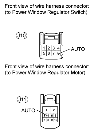
Disconnect the J10 switch connector.
-
Disconnect the J11 motor connector.
-
Measure the resistance according to the value(s) in the table below.
Standard Resistance Tester Connection Condition Specified Condition J10-8 (AUTO) - J11-4 (AUTO) Always Below 1 Ω J10-8 (AUTO) or J11-4 (AUTO) - Body ground Always 10 kΩ or higher
NG
REPAIR OR REPLACE HARNESS OR CONNECTOR
OK
-
-
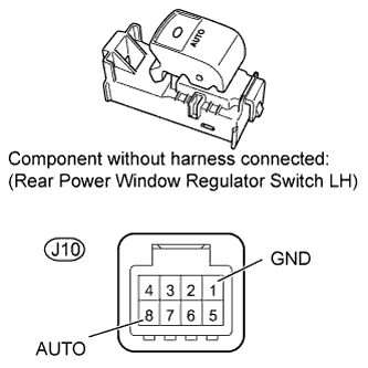
INSPECT REAR POWER WINDOW REGULATOR SWITCH ASSEMBLY LH
-
Remove the rear power window regulator switch Click here.
-
Measure the resistance according to the value(s) in the table below.
Standard Resistance Tester Connection Switch Condition Specified Condition J10-8 (AUTO) - J10-1 (GND) Auto up/down operation Below 1 Ω
NG
REPLACE REAR POWER WINDOW REGULATOR SWITCH ASSEMBLY Click here
OK
REPLACE REAR POWER WINDOW REGULATOR MOTOR ASSEMBLY LH Click here
-