POWER WINDOW REGULATOR MOTOR (for Front Door) REMOVAL

Tech Tips
-
Use the same procedure for the RH and LH sides.
-
The procedure listed below is for the LH side.
-
PRECAUTION
Note
After turning the ignition switch off, waiting time may be required before disconnecting the cable from the battery terminal. Therefore, make sure to read the disconnecting the cable from the battery terminal notice before proceeding with work Click here.
-
DISCONNECT CABLE FROM NEGATIVE BATTERY TERMINAL
CAUTION:
Wait at least 90 seconds after disconnecting the cable from the negative (-) battery terminal to disable the SRS system.
Note
When disconnecting the cable, some systems need to be initialized after the cable is reconnected Click here.
-
REMOVE FRONT LOWER DOOR FRAME BRACKET GARNISH
-
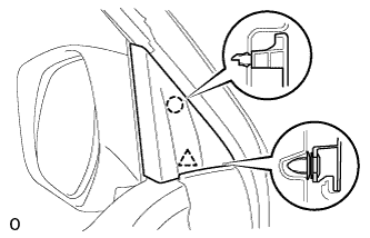
Detach the clip and claw, and remove the front door lower frame bracket garnish LH.
-
-
REMOVE FRONT DOOR INSIDE HANDLE BEZEL
-
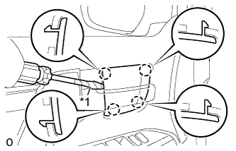
Text in Illustration *1 Protective Tape Using a screwdriver, detach the 4 claws and remove the front door inside handle bezel LH.
Tech Tips
Tape the screwdriver tip before use.
-
-
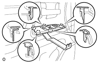
REMOVE FRONT DOOR ARMREST BASE PANEL ASSEMBLY
-
Using a moulding remover, detach the 5 claws.
-
Disconnect the connector and remove the armrest base panel.
-
-
REMOVE DOOR ASSIST GRIP COVER
-
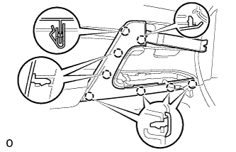
Using a moulding remover, detach the 8 claws and remove the door assist grip cover LH.
-
-
REMOVE FRONT DOOR TRIM BOARD SUB-ASSEMBLY
-
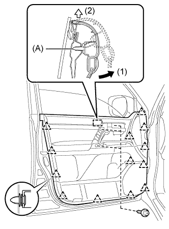
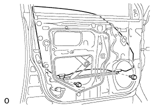
Remove the 3 screws.
-
Remove the 13 clips.
-
Remove the front inner door glass weatherstrip LH together with the front door trim board sub-assembly LH by pulling them upward in the order shown in the illustration.
Tech Tips
Make sure that the pin labeled A in the illustration is detached from the door panel.
-
Disconnect the connector.
-
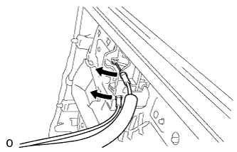
Disconnect the 2 cables from the front door inside handle sub-assembly LH.
-
-
REMOVE FRONT NO. 1 SPEAKER ASSEMBLY
-
Disconnect the speaker connector.
-
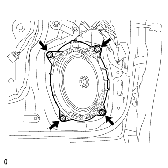
Remove the 4 screws and speaker.
Note
Do not touch the cone part of the speaker.
-
-
REMOVE FRONT DOOR SERVICE HOLE COVER
-
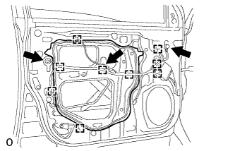
Using a clip remover, detach the 9 clamps.
-
Remove the bolt and disconnect the 2 connectors.
-
Remove the front door service hole cover LH.
Tech Tips
Remove the remaining tape on the door.
-
-
REMOVE FRONT DOOR GLASS SUB-ASSEMBLY
-
Driver Side:
Temporarily install the multiplex network master switch.
-
Passenger Side:
Temporarily install the power window regulator switch assembly.
-
Connect the cable to the negative (-) battery terminal.
-
Move the front door glass sub-assembly until the bolts appear in the service holes.
-
Disconnect the cable from the negative (-) battery terminal.
-
Remove the 2 bolts.
Note
Be careful when removing the bolts as the glass may fall and become damaged.
-
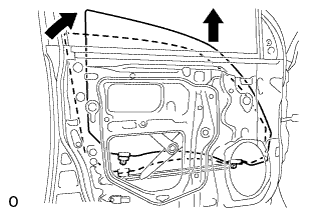
Remove the front door glass sub-assembly in the direction indicated by the arrows in the illustration.
Tech Tips
Remove the front door glass sub-assembly upward.
Note
Be careful not to damage the glass.
-
Driver Side:
Remove the multiplex network master switch.
-
Passenger Side:
Remove the power window regulator switch assembly.
-
-
REMOVE FRONT DOOR WINDOW REGULATOR SUB-ASSEMBLY
-
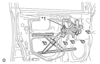
Text in Illustration *1 Temporary Bolt Loosen the temporary bolt.
-
Remove the 5 bolts, and front door window regulator sub-assembly LH.
Tech Tips
Remove the front door window regulator sub-assembly LH through the service hole.
Note
Be careful when removing the bolts as the front door window regulator sub-assembly LH may fall and become damaged.
-
Remove the front door window regulator sub-assembly LH and the front power window regulator motor assembly LH as a unit.
-
Remove the temporary bolt from the front door window regulator sub-assembly LH.
-
-
REMOVE FRONT POWER WINDOW REGULATOR MOTOR ASSEMBLY
-
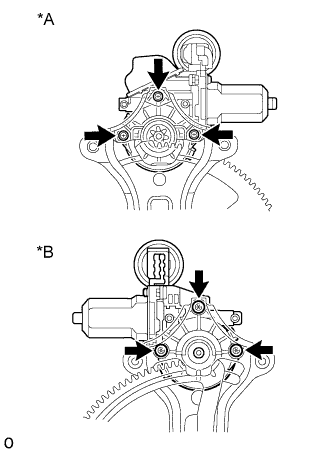
Text in Illustration *A for Models with Jam Protection Function on 4 Windows *B for Front Passenger Side, for Models with Jam Protection Function on Driver Door Window Only Using a T25 "TORX" driver, remove the 3 screws and motor.
Note
Be careful when removing the screws as the motor may fall and become damaged.
-