POWER WINDOW REGULATOR MOTOR (for Front Door) INSTALLATION

Tech Tips
-
Use the same procedure for the RH and LH sides.
-
The procedure listed below is for the LH side.
-
A bolt without a torque specification is shown in the standard bolt chart Click here.
-
INSTALL FRONT POWER WINDOW REGULATOR MOTOR ASSEMBLY LH
-
Apply MP grease to the sliding and rotating areas of the regulator motor.
-
Using a T25 ''TORX'' driver, install the motor with the 3 screws.
- Torque:
- 5.4 N*m { 55 kgf*cm, 48 in.*lbf }
Tech Tips
A new front window regulator motor uses self-tapping screws to thread new installation holes when the self-tapping screws are inserted.
-
-
INSTALL FRONT DOOR WINDOW REGULATOR SUB-ASSEMBLY
-
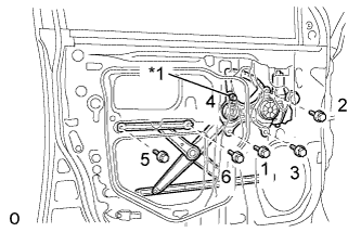
Text in Illustration *1 Temporary Bolt Apply MP grease to the sliding and rotating areas of the front door window regulator sub-assembly LH.
Note
Do not apply grease to the spring of the front door window regulator sub-assembly LH.
-
Loosely install the temporary bolt onto the front door window regulator sub-assembly LH.
-
Insert the front door window regulator sub-assembly LH into the door panel. Use the temporary bolt to hang the front door window regulator sub-assembly LH on the door panel.
Note
Be careful not to drop the front door window regulator sub-assembly LH as it may become damaged.
-
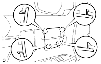
Temporarily install the front door window regulator sub-assembly LH with the 5 bolts.
-
Tighten the 6 bolts in the order shown in the illustration.
- Torque:
- 8.0 N*m { 82 kgf*cm, 71 in.*lbf }
-
-
INSTALL FRONT DOOR GLASS SUB-ASSEMBLY
-
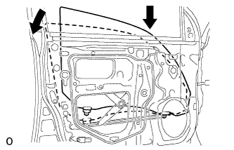
Insert the front door glass sub-assembly LH into the door panel along the glass run as indicated by the arrows in the illustration.
Note
Be careful not to damage the glass.
-
Install the front door glass sub-assembly LH to the front door window regulator sub-assembly LH with the 2 bolts.
- Torque:
- 8.0 N*m { 82 kgf*cm, 71 in.*lbf }
-
-
INSTALL FRONT DOOR SERVICE HOLE COVER
-
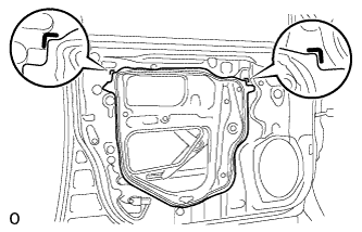
Apply butyl tape to the door.
-
Pass the front door lock remote control cable assembly LH and front door inside locking cable assembly LH through a new front door service hole cover LH.
Note
-
When installing the front door service hole cover LH, pull the links and connectors through the front door service hole cover LH.
-
There should be no wrinkles or folds after attaching the front door service hole cover LH.
-
After attaching the front door service hole cover LH, check the sealing quality.
-
-
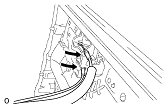
Connect the 2 connectors.
-
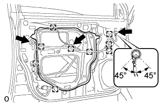
Attach the 9 clamps.
-
Install the bolt as shown in the illustration.
- Torque:
- 8.4 N*m { 86 kgf*cm, 74 in.*lbf }
-
-
INSTALL FRONT NO. 1 SPEAKER ASSEMBLY
-
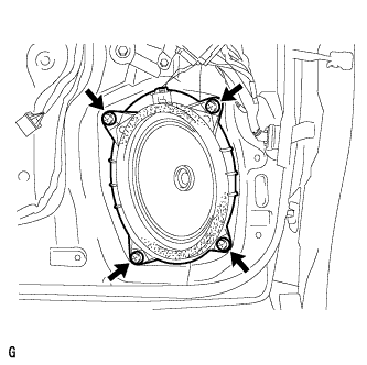
Connect the speaker connector.
-
Install the speaker with the 4 screws.
Note
Do not touch the cone part of the speaker.
-
-
INSTALL FRONT DOOR TRIM BOARD SUB-ASSEMBLY
-
Connect the connector.
-
Connect the front door lock remote control cable assembly LH and front door inside locking cable assembly LH to the front door inside handle sub-assembly LH.
-
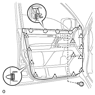
Attach the 4 claws and 13 clips to install the front door trim board sub-assembly LH.
-
Install the 3 screws.
-
-
INSTALL DOOR ASSIST GRIP COVER
-
Attach the 8 claws to install the door assist grip cover LH to the front door trim board sub-assembly LH.
-
-
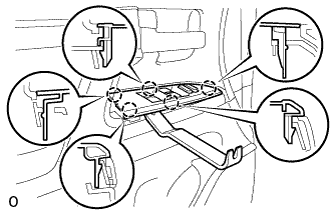
INSTALL FRONT DOOR ARMREST BASE PANEL ASSEMBLY
-
Using a moulding remover, detach the 5 claws.
-
Disconnect the connector and remove the armrest base panel.
-
-
INSTALL FRONT DOOR INSIDE HANDLE BEZEL
-
Attach the 4 claws to install the front door inside handle bezel LH.
-
-
INSTALL FRONT LOWER DOOR FRAME BRACKET GARNISH
-
Attach the clip and claw, and install the front door lower frame bracket garnish LH.
-
-
CONNECT CABLE TO NEGATIVE BATTERY TERMINAL
Note
When disconnecting the cable, some systems need to be initialized after the cable is reconnected Click here.