METER / GAUGE SYSTEM Voltage Meter Malfunction
DESCRIPTION
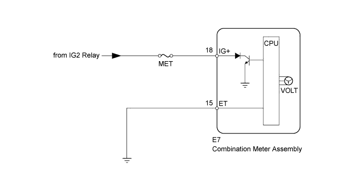
The voltmeter indicates the voltage applied to the IG+ terminal of the combination meter.
WIRING DIAGRAM
INSPECTION PROCEDURE
PROCEDURE
-
INSPECT FUSE (MET)
-
Remove the MET fuse from the engine room relay block.
-
Measure the resistance according to the value(s) in the table below.
Standard Resistance Tester Connection Condition Specified Condition MET fuse Always Below 1 Ω
NG 
REPLACE FUSE
OK 
-
-
PERFORM ACTIVE TEST USING INTELLIGENT TESTER (VOLTMETER)
-
Operate the intelligent tester according to the display and select Active Test Click here.
Combination Meter Tester Display Test Part Control Range Diagnostic Note Volt meter Operation Voltmeter 0, 3, 6, 9, 12, 15, or 18 Perform the test with the vehicle stopped and engine idling. OK Needle indication is normal. Result Result Proceed to OK A NG (w/ Multi-information Display) B NG (w/o Multi-information Display) C
B
REPLACE COMBINATION METER ASSEMBLY Click here
C
REPLACE COMBINATION METER ASSEMBLY Click here
A
-
-
CHECK HARNESS AND CONNECTOR (COMBINATION METER - BATTERY AND BODY GROUND)
-
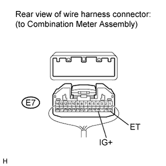
Disconnect the E7 meter connector.
-
Measure the resistance and voltage according to the value(s) in the tables below.
Standard Resistance Tester Connection Condition Specified Condition E7-15 (ET) - Body ground Always Below 1 Ω Standard Voltage Tester Connection Switch Condition Specified Condition E7-18 (IG+) Ignition switch ON 11 to 14 V Ignition switch off Below 1 V Result Result Proceed to NG A OK (w/ Multi-information Display) B OK (w/o Multi-information Display) C
B
REPLACE COMBINATION METER ASSEMBLY Click here
C
REPLACE COMBINATION METER ASSEMBLY Click here
A 
REPAIR OR REPLACE HARNESS OR CONNECTOR
-