THEFT DETERRENT SYSTEM (w/ Entry and Start System) Glass Breakage Sensor Circuit
DESCRIPTION
When the glass breakage sensor detects that the back door glass, quarter window glass LH or quarter window glass RH is tapped or broken, the sensor will set off the alarm for 30 seconds.
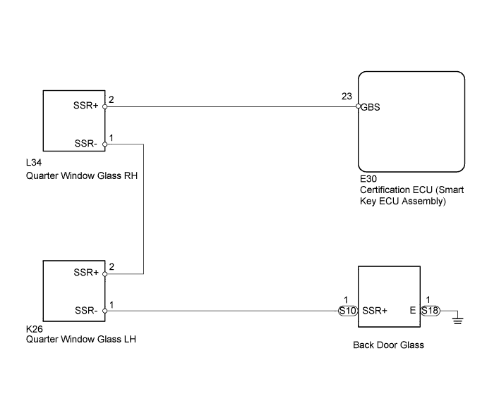
WIRING DIAGRAM
INSPECTION PROCEDURE
PROCEDURE
-
READ VALUE USING INTELLIGENT TESTER (GLASS BREAK SENSOR)
-
Using the intelligent tester, read the Data List.
Entry&Start Tester Display Measurement Item/Range Normal Condition Diagnostic Note Glass break sensor detection Glass breakage sensor detection / ON or OFF ON: Glass breakage sensor operates
OFF: Glass breakage sensor does not operate
- OK ON (glass breakage sensor operates) appears on screen.
NG 
INSPECT CERTIFICATION ECU (SMART KEY ECU ASSEMBLY) Click here
OK 
REPLACE CERTIFICATION ECU (SMART KEY ECU ASSEMBLY)
-
-
INSPECT CERTIFICATION ECU (SMART KEY ECU ASSEMBLY)
-
Disconnect the E30 ECU connector.
-
Measure the voltage according to the value(s) in the table below.
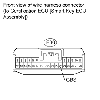
Standard Voltage Tester Connection Condition Specified Condition E30-23 (GBS) - Body ground Always Below 1.5 V
NG 
REPLACE CERTIFICATION ECU (SMART KEY ECU ASSEMBLY)
OK 
-
-
CHECK HARNESS AND CONNECTOR (CERTIFICATION ECU [SMART KEY ECU ASSEMBLY] - GLASS BREAKAGE SENSOR)
-
Disconnect the E30 ECU connector.
-
Measure the resistance according to the value(s) in the table below.
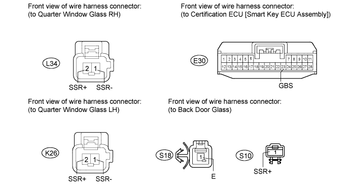
Standard Resistance Tester Connection Condition Specified Condition E30-23 (GBS) - L34-2 (SSR+) Always Below 1 Ω L34-1 (SSR-) - K26-2 (SSR+) Always Below 1 Ω K26-1 (SSR-) - S10-1 (SSR+) Always Below 1 Ω S18-1 (E) - Body ground Always Below 1 Ω
NG
REPAIR OR REPLACE HARNESS OR CONNECTOR
OK
-
-
INSPECT QUARTER WINDOW GLASS RH
-

Disconnect the L34 sensor connector.
-
Measure the resistance according to the value(s) in the table below.
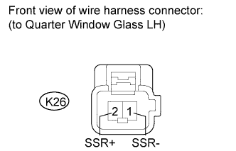
Standard Resistance Tester Connection Condition Specified Condition 1 (SSR-) - 2 (SSR+) Always Below 1 Ω
NG
REPLACE REAR DOOR QUARTER WINDOW GLASS RH
OK
-
-
INSPECT QUARTER WINDOW GLASS LH
-
Disconnect the K26 sensor connector.
-
Measure the resistance according to the value(s) in the table below.
Standard Resistance Tester Connection Condition Specified Condition 1 (SSR-) - 2 (SSR+) Always Below 1 Ω
NG
REPLACE REAR DOOR QUARTER WINDOW GLASS LH
OK
-
-
INSPECT BACK DOOR GLASS
-
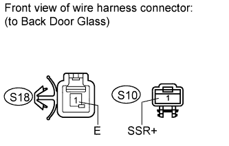
Disconnect the S10 sensor connector.
-
Disconnect the S18 defogger connector.
-
Measure the resistance according to the value(s) in the table below.
Standard Resistance Tester Connection Condition Specified Condition S10-1 (SSR+) - S18-1 (E) Always Below 1 Ω
NG
REPLACE BACK DOOR GLASS
OK
REPLACE CERTIFICATION ECU (SMART KEY ECU ASSEMBLY)
-