THEFT DETERRENT SYSTEM (w/ Entry and Start System) Security Indicator Light Circuit
DESCRIPTION
-
When the theft deterrent system is in the disarmed state, the security indicator will flash continuously if the immobiliser system is set, or not illuminate if the immobiliser system is not set.
When the theft deterrent system is in the armed state, the immobiliser system is automatically set and the security indicator will flash continuously.
When the theft deterrent system is in the arming preparation state and alarm sounding state, the certification ECU (smart key ECU assembly) causes the security indicator to be illuminated.
WIRING DIAGRAM
INSPECTION PROCEDURE
PROCEDURE
-
PERFORM ACTIVE TEST USING INTELLIGENT TESTER (SECURITY INDICATOR)
-
Connect the intelligent tester to the DLC3.
-
Turn the engine switch on (IG).
-
Turn the intelligent tester on.
-
Enter the following menus: Body / Entry&Start / Active Test.
-
According to the display on the intelligent tester, perform the Active Test.
Entry&Start Tester Display Test Part Control Range Diagnostic Note Security Indicator Security indicator ON / OFF - OK Security indicator illuminates.
NG 
CHECK VEHICLE EQUIPMENT Click here
OK 
REPLACE CERTIFICATION ECU (SMART KEY ECU ASSEMBLY)
-
-
CHECK VEHICLE EQUIPMENT
-
Check if the multi-display is equipped on the vehicle.
Result Result Proceed to w/ Multi-display A w/o Multi-display B
B
CHECK HARNESS AND CONNECTOR (CLOCK - CERTIFICATION ECU [SMART KEY ECU ASSEMBLY] AND BODY GROUND) Click here
A 
-
-
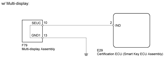
CHECK HARNESS AND CONNECTOR (MULTI-DISPLAY - CERTIFICATION ECU [SMART KEY ECU ASSEMBLY] AND BODY GROUND)
-
Disconnect the F79 multi-display assembly connector.
-
Disconnect the E29 certification ECU (smart key ECU assembly) connector.
-
Measure the resistance according to the value(s) in the table below.
Standard Resistance Tester Connection Condition Specified Condition F79-10 (SEUC) - E29-2 (IND) Always Below 1 Ω F79-13 (GND1) - Body ground Always Below 1 Ω F79-10 (SEUC) - Body ground Always 10 kΩ or higher
NG 
REPAIR OR REPLACE HARNESS OR CONNECTOR
OK
-
-
PERFORM ACTIVE TEST USING INTELLIGENT TESTER (SECURITY INDICATOR)
-
Disconnect the F79 multi-display assembly connector.
-
Connect the intelligent tester to the DLC3.
-
Turn the engine switch on (IG).
-
Turn the intelligent tester on.
-
Enter the following menus: Body / Entry & Start / Active Test.
-
Operate the certification ECU (smart key ECU assembly) using the active test function and measure the voltage according to the value(s) in the table below.
Standard voltage Tester Connection Tester Operation Specified Condition E29-2 (IND) - Body ground Security Indicator ON 11 to 14 V E29-2 (IND) - Body ground Security Indicator OFF Below 1 V Tech Tips
Before performing this inspection, check that the battery voltage is between 11 and 14 V (not depleted).
NG
REPLACE CERTIFICATION ECU (SMART KEY ECU ASSEMBLY)
OK
REPLACE MULTI-DISPLAY Click here
-
-
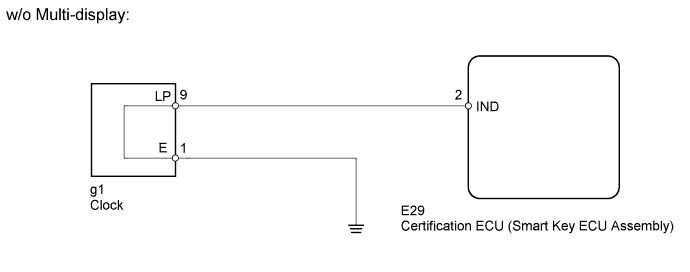
CHECK HARNESS AND CONNECTOR (CLOCK - CERTIFICATION ECU [SMART KEY ECU ASSEMBLY] AND BODY GROUND)
-
Disconnect the g1 clock connector.
-
Disconnect the E29 certification ECU (smart key ECU assembly) connector.
-
Measure the resistance according to the value(s) in the table below.
Standard Resistance Tester Connection Condition Specified Condition g1-9 (LP) - E29-2 (IND) Always Below 1 Ω g1-1 (E) - Body ground Always Below 1 Ω g1-9 (LP) - Body ground Always 10 kΩ or higher
NG
REPAIR OR REPLACE HARNESS OR CONNECTOR
OK
-
-
PERFORM ACTIVE TEST USING INTELLIGENT TESTER (SECURITY INDICATOR)
-
Disconnect the g1 clock connector.
-
Connect the intelligent tester to the DLC3.
-
Turn the engine switch on (IG).
-
Turn the intelligent tester on.
-
Enter the following menus: Body / Entry & Start / Active Test.
-
Operate the certification ECU (smart key ECU assembly) using the active test function and measure the voltage according to the value(s) in the table below.
Standard voltage Tester Connection Tester Operation Specified Condition g1-9 (LP) - Body ground Security Indicator ON 11 to 14 V g1-9 (LP) - Body ground Security Indicator OFF Below 1 V Tech Tips
Before performing this inspection, check that the battery voltage is between 11 and 14 V (not depleted).
NG
REPLACE CERTIFICATION ECU (SMART KEY ECU ASSEMBLY)
OK
REPLACE CLOCK Click here
-