DESCRIPTION
The antenna coil receives key code signals from the transponder chip in the key grip. The antenna coil is built into the transponder key amplifier, which amplifies the key code signals and outputs the signals to the transponder key ECU assembly.
This DTC is stored when there is an open or short in the antenna coil.
| DTC Code | DTC Detection Condition | Trouble Area | DTC Output Confirmation Operation |
|---|---|---|---|
| B2784 | The antenna coil built into the transponder key amplifier is open or shorted (determined by communication with the transponder key ECU assembly) (1 trip detection logic*).
|
|
Insert the key into the ignition key cylinder. |
-
*: Only output while a malfunction is present.
| Vehicle Condition when Malfunction Detected | Fail-safe Operation when Malfunction Detected |
|---|---|
| Engine cannot be started | - |
| DTC Code | Data List and Active Test |
|---|---|
| B2784 | Antenna Coil Status |
INSPECTION PROCEDURE
-
When replacing the transponder key ECU assembly, refer to the Service Bulletin.
-
After performing repairs, perform the operation that fulfills the DTC output confirmation operation, and then confirm that no DTCs are output again.
PROCEDURE
- Click here
CLEAR DTC
-
Clear the DTCs (Click here).
- NEXTClick here
-
- Click here
CHECK FOR DTC
-
Check for DTCs (Click here).
Tip:Before checking for DTCs, perform the "DTC Output Confirmation Operation" procedure.
OK DTC B2784 is not output.
- OKClick here
- NGClick here
-
- Click here
CHECK TRANSPONDER KEY AMPLIFIER (OUTPUT)
-
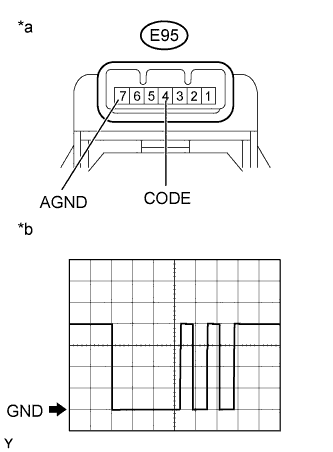
Using an oscilloscope, check the waveform.
Table 3. Text in Illustration *a Component with harness connected
(Transponder Key Amplifier)
*b Waveform
-
Waveform (Reference)
Table 4. Measurement Condition Item Content Tester Connection E95-4 (CODE) - E95-7 (AGND) Tool Setting 1 V/DIV., 100 μs./DIV. Condition Key inserted in ignition key cylinder OK Waveform is output normally (refer to illustration).
-
- OKClick here
- NGClick here
-
- Click here
REPLACE TRANSPONDER KEY ECU ASSEMBLY
-
Replace the transponder key ECU assembly (refer to the Service Bulletin).
- NEXTClick here
-
- Click here
REGISTER KEY
-
Reregister the key (refer to the Service Bulletin).
- NEXTClick here
-
- Click here
REGISTER ECU COMMUNICATION ID
-
Register the ECU communication ID (refer to the Service Bulletin).
- NEXTClick here
-
- Click here
CLEAR DTC
-
Clear the DTCs (Click here).
- NEXTClick here
-
- Click here
CHECK FOR DTC
-
Check for DTCs (Click here).
Tip:Before checking for DTCs, perform the "DTC Output Confirmation Operation" procedure.
OK DTC B2784 is not output.
- OKClick here
- NGClick here
-
- Click here
USE SIMULATION METHOD TO CHECKClick here
- Click here
REPLACE TRANSPONDER KEY AMPLIFIERClick here
- Click here
REPLACE TRANSPONDER KEY AMPLIFIERClick here
- Click here
END (TRANSPONDER KEY ECU ASSEMBLY WAS DEFECTIVE)