ENTRY AND START SYSTEM (for Start Function), Diagnostic DTC:B2278

| DTC Code | DTC Name |
|---|---|
| B2278 | Engine Switch Circuit Malfunction |
DESCRIPTION
This DTC is stored when: 1) a malfunction is detected between the main body ECU and the engine switch; or 2) either of the switches inside the engine switch is malfunctioning.
| DTC Code | Detection Condition | Trouble Area |
|---|---|---|
| B2278 | Communication is abnormal between the main body ECU and engine switch or the engine switch is defective. |
|
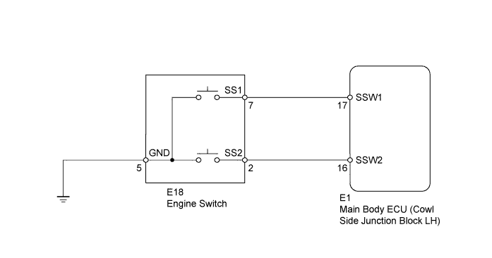
WIRING DIAGRAM
INSPECTION PROCEDURE
PROCEDURE
-
READ VALUE USING INTELLIGENT TESTER (START SWITCH 1, 2)
-
Use the Data List to check if the engine switch is functioning properly.
Main Body Tester Display Measurement Item/Range Normal Condition Diagnostic Note Start Switch 1 Start Switch 1/ON or OFF ON: Engine switch on (IG)
OFF: Engine switch off
- Start Switch 2 Start Switch 2/ON or OFF ON: Engine switch on (IG)
OFF: Engine switch off
- OK When the engine switch is turned on (IG), ON is displayed on the intelligent tester.
NG 
INSPECT ENGINE SWITCH Click here
OK 
-
-
CHECK WHETHER DTC OUTPUT RECURS
-
Clear the DTCs Click here.
-
Turn the engine switch on (IG), and check whether DTC B2278 is output.
Result Result Proceed to No DTC output A DTC B2278 output B
B 
REPLACE MAIN BODY ECU
A 
USE SIMULATION METHOD TO CHECK Click here
-
-
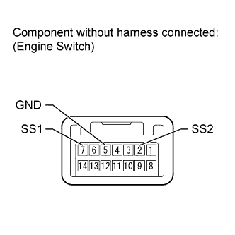
INSPECT ENGINE SWITCH
-
Disconnect the E18 engine switch connector.
-
Measure the resistance according to the value(s) in the table below.
Standard Resistance Tester Connection Switch Condition Specified Condition 7 (SS1) - 5 (GND) Pushed Below 1 Ω 2 (SS2) - 5 (GND) Pushed Below 1 Ω 7 (SS1) - 5 (GND) Not pushed 10 kΩ or higher 2 (SS2) - 5 (GND) Not pushed 10 kΩ or higher Result Result Proceed to Within specified range A Outside specified range (for 1GR-FE) B Outside specified range (for 1UR-FE) C Outside specified range (for 3UR-FE) D Outside specified range (for 1VD-FTV) E
B
REPLACE ENGINE SWITCH Click here
C
REPLACE ENGINE SWITCH Click here
D
REPLACE ENGINE SWITCH Click here
E
REPLACE ENGINE SWITCH Click here
A
-
-
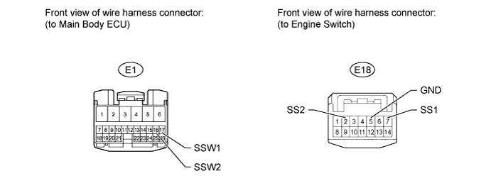
CHECK HARNESS AND CONNECTOR (MAIN BODY ECU - ENGINE SWITCH AND BODY GROUND)
-
Disconnect the E1 main body ECU connector.
-
Disconnect the E18 engine switch connector.
-
Measure the resistance according to the value(s) in the table below.
Standard Resistance Tester Connection Condition Specified Condition E1-17 (SSW1) - E18-7 (SS1) Always Below 1 Ω E1-16 (SSW2) - E18-2 (SS2) Always Below 1 Ω E18-5 (GND) - Body ground Always Below 1 Ω E1-17 (SSW1) or E18-7 (SS1) - Body ground Always 10 kΩ or higher E1-16 (SSW2) or E18-2 (SS2) - Body ground Always 10 kΩ or higher
NG
REPAIR OR REPLACE HARNESS OR CONNECTOR
OK
REPLACE MAIN BODY ECU
-