ENTRY AND START SYSTEM (for Entry Function) Back Door Entry Unlock Function does not Operate
DESCRIPTION
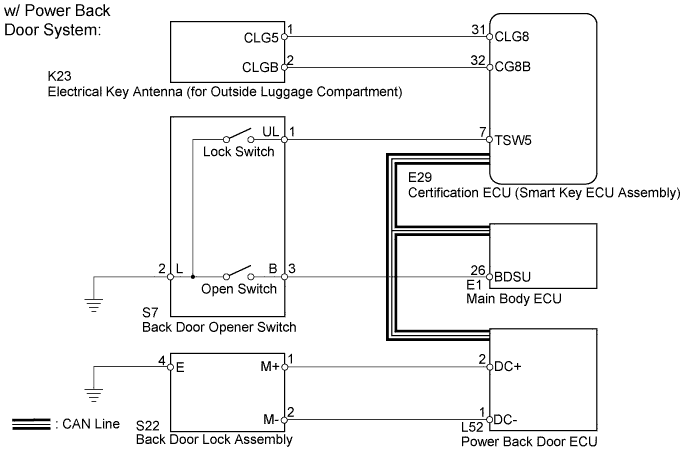
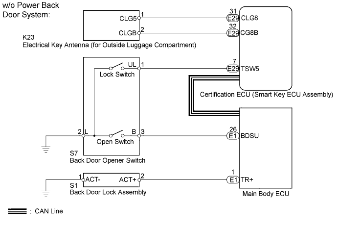
When the back door opener switch is turned on, the certification ECU (smart key ECU assembly) uses the electrical key antenna (for outside luggage compartment) and antenna to output a request signal to the outside of the vehicle for a distance of approximately 1.0 m (3.28 ft.) from the back door. A key near the back door detects this request and transmits its ID code. The door control receiver receives the ID code and sends this ID code to the certification ECU (smart key ECU assembly). The certification ECU (smart key ECU assembly) checks if the ID code is valid. When the ID code is valid, the certification ECU (smart key ECU assembly) sends a back door open signal to the main body ECU using the CAN communication line and stops outputting request signals. The main body ECU then unlocks the back door.
WIRING DIAGRAM
INSPECTION PROCEDURE
Note
Before performing the inspection, check that there are no problems related to the "CAN Communication System" and "LIN Communication System".
PROCEDURE
-
CHECK POWER DOOR LOCK OPERATION
-
When the door control switch of the master switch assembly is operated, check that the locked doors unlock.
OK Door locks operate normally.
NG 
GO TO POWER DOOR LOCK CONTROL SYSTEM Click here
OK 
-
-
CHECK VEHICLE EQUIPMENT
-
Check if the power back door is equipped on the vehicle.
Result Result Proceed to w/ Power Back Door System A w/o Power Back Door System B
B 
READ VALUE USING INTELLIGENT TESTER (DOOR LOCK POSITION SWITCH) Click here
A
-
-
CHECK POWER BACK DOOR OPERATION
-
When the power back door switch is operated, check that the power back door opens.
OK Power back door system is normal. Result Result Proceed to Power back door system is abnormal A Power back door system is normal B
B
READ VALUE USING INTELLIGENT TESTER (BACK DOOR HANDLE SW) Click here
A 
GO TO POWER BACK DOOR SYSTEM Click here
-
-
READ VALUE USING INTELLIGENT TESTER (DOOR LOCK POSITION SWITCH)
-
Connect the intelligent tester to the DLC3.
-
Turn the engine switch on (IG).
-
Turn the intelligent tester on.
-
Enter the following menus: Body / Main Body / Data List.
-
Read the Data List according to the display on the intelligent tester.
Main Body Tester Display Measurement Item / Range Normal Condition Diagnostic Note Back Lock Pos switch Back door lock position switch signal / ON or OFF ON: Back door unlocked
OFF: Back door locked
- OK On the intelligent tester screen, the display changes between ON and OFF as shown in the chart above.
NG
GO TO POWER DOOR LOCK CONTROL SYSTEM (Proceed to Only Back Door LOCK/UNLOCK Functions do not Operate) Click here
OK
-
-
READ VALUE USING INTELLIGENT TESTER (BACK DOOR HANDLE SW)
-
Using the intelligent tester, read the Data List.
Main Body Tester Display Measurement Item/Range Normal Condition Diagnostic Note Back Door Handle SW Back door opener switch / ON or OFF ON: Back door open switch is pushed
OFF: Back door open switch is not pushed
- OK "ON" (switch is pushed) and "OFF" (switch is not pushed) appears on the screen.
NG
CHECK BACK DOOR OPENER SWITCH Click here
OK
REPLACE CERTIFICATION ECU (SMART KEY ECU ASSEMBLY)
-
-
CHECK BACK DOOR OPENER SWITCH
-
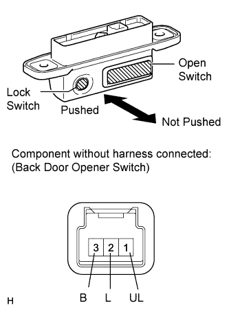
Measure the resistance according to the value(s) in the table below.
Standard Resistance Tester Connection Switch Condition Specified Condition 3 (B) - 2 (L) Not pushed 10 kΩ or higher 3 (B) - 2 (L) Open switch pushed Below 1 Ω
NG
REPLACE BACK DOOR OPENER SWITCH Click here
OK
-
-
CHECK HARNESS AND CONNECTOR (MAIN BODY ECU - BACK DOOR OPENER SWITCH)
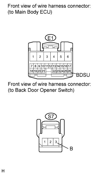
-
Disconnect the E1 ECU connector.
-
Disconnect the S7 switch connector.
-
Measure the resistance according to the value(s) in the table below.
Standard Resistance Tester Connection Condition Specified Condition E1-26 (BDSU) - S7-3 (B) Always Below 1 Ω E1-26 (BDSU) or S7-3 (B) - Body ground Always 10 kΩ or higher
NG
REPAIR OR REPLACE HARNESS OR CONNECTOR
OK
REPLACE CERTIFICATION ECU (SMART KEY ECU ASSEMBLY)
-