Click here
-
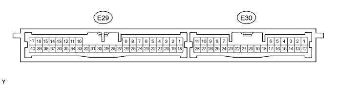
CHECK CERTIFICATION ECU (SMART KEY ECU ASSEMBLY)
-
Disconnect the E29 ECU connector.
-
Measure the resistance and voltage of the wire harness side connector.
Terminal No. (Symbol) Wiring Color Terminal Description Condition Specified Condition E29-17 (E) - Body ground W-B - Body ground Ground Always Below 1 Ω E29-1 (+B) - Body ground B - Body ground +B power supply Always 11 to 14 V E29-18 (IG) - Body ground B - Body ground Ignition power supply Engine switch off Below 1 V Engine switch on (IG) 11 to 14 V E29-3 (TSW1) - E29-17 (E) G - W-B Door outside handle (driver side) lock switch signal Switch released 10 kΩ or higher Switch pressed in Below 1 Ω E29-4 (TSW2) - E29-17 (E) BR - W-B Door outside handle (front passenger side) lock switch signal Switch released 10 kΩ or higher Switch pressed in Below 1 Ω E30-25 (TSW3) - E29-17 (E)*3 G - W-B
-
Door outside handle (rear LH) lock switch signal*1
-
Door outside handle (rear RH) lock switch signal*2
Switch released 10 kΩ or higher Switch pressed in Below 1 Ω E30-26 (TSW4) - E29-17 (E)*3 G - W-B
-
Door outside handle (rear RH) lock switch signal*1
-
Door outside handle (rear LH) lock switch signal*2
Switch released 10 kΩ or higher Switch pressed in Below 1 Ω E29-7 (TSW5) - E29-17 (E) L - W-B Back door lock switch signal Switch released 10 kΩ or higher Switch pressed in Below 1 Ω E29-10 (LIN) - E29-17 (E) GR - W-B LIN line Always 10 kΩ or higher E29-27 (CANH) - E29-17 (E) LG - W-B CAN line Always 10 kΩ or higher E29-28 (CANL) - E29-17 (E) R - W-B CAN line Always 10 kΩ or higher Tip:
-
*1: for LHD
-
*2: for RHD
-
*3: For vehicles with entry function for rear doors.
-
If the result is not as specified, the wire harness side may have a malfunction.
-
-
Reconnect the E29 ECU connector.
-
Measure the voltage of the connector.
Terminal No. (Symbol) Wiring Color Terminal Description Condition Specified Condition E29-33 (CLG1) - E29-34 (CG1B) L - W Door electrical key oscillator (driver side) sensor signal All doors closed, all doors locked and engine switch off Alternating between 5 V and below 1 V Door unlocked or door open Below 1 V E29-22 (SEN1) - E29-17 (E) R - W-B Touch sensor detection signal Door outside handle touched 11 to 14 V Door outside handle not touched Below 1 V E29-5 (SEL1) - E29-17 (E) Y - W-B Touch sensor activation control signal Key at least 5 m (16.4 ft.) away from door 11 to 14 V Key moved near outside door handle Below 1 V E29-35 (CLG2) - E29-36 (CG2B) L - R Door electrical key oscillator (front passenger side) sensor signal All doors closed, all doors locked and engine switch off Alternating between 5 V and below 1 V Door unlocked or door open Below 1 V E29-23 (SEN2) - E29-17 (E) R - W-B Touch sensor detection signal Door outside handle touched 11 to 14 V Door outside handle not touched Below 1 V E29-6 (SEL2) - E29-17 (E) Y - W-B Touch sensor activation control signal Key at least 5 m (16.4 ft.) away from door 11 to 14 V Key moved near outside door handle Below 1 V E30-8 (CLG3) - E30-9 (CG3B)*3 L - W
-
Door electrical key oscillator (rear LH) sensor signal*1
-
Door electrical key oscillator (rear RH) sensor signal*2
All doors closed, all doors locked and engine switch off Alternating between 5 V and below 1 V Door unlocked or door open Below 1 V E30-28 (SEN3) - E29-17 (E)*3 R - W-B Touch sensor detection signal Door outside handle touched 11 to 14 V Door outside handle not touched Below 1 V E30-1 (SEL3) - E29-17 (E)*3 Y - W-B Touch sensor activation control signal Key at least 5 m (16.4 ft.) away from door 11 to 14 V Key moved near outside door handle Below 1 V E30-10 (CLG4) - E30-11 (CG4B)*3 L - W
-
Door electrical key oscillator (rear RH) sensor signal*1
-
Door electrical key oscillator (rear LH) sensor signal*2
All doors closed, all doors locked and engine switch off Alternating between 5 V and below 1 V Door unlocked or door open Below 1 V E30-27 (SEN4) - E29-17 (E)*3 R - W-B Touch sensor detection signal Door outside handle touched 11 to 14 V Door outside handle not touched Below 1 V E30-2 (SEL4) - E29-17 (E)*3 Y - W-B Touch sensor activation control signal Key at least 5 m (16.4 ft.) away from door 11 to 14 V Key moved near outside door handle Below 1 V E29-11 (CLG5) - E29-12 (CG5B) SB - V Indoor electrical key antenna (for front) sensor signal 30 seconds after driver side door opened and closed, engine switch off Alternating between 5 V and below 1 V Within 30 seconds after driver side door opened and closed, engine switch off Below 1 V E29-13 (CLG6) - E29-14 (CG6B) R - SB Indoor electrical key antenna (for rear 1) sensor signal 30 seconds after driver side door opened and closed, engine switch off Alternating between 5 V and below 1 V Within 30 seconds after driver side door opened and closed, engine switch off Below 1 V E29-15 (CLG7) - E29-16 (CG7B) GR - W Indoor electrical key antenna (for rear 2) sensor signal 30 seconds after driver side door opened and closed, engine switch off Alternating between 5 V and below 1 V Within 30 seconds after driver side door opened and closed, engine switch off Below 1 V E29-31 (CLG8) - E29-32 (CG8B) G - GR Back door electrical key antenna (for outer) sensor signal Back door opener switch off Alternating between 5 V and below 1 V Back door opener switch on Below 1 V E29-29 (RCO) - E29-17 (E) B - W-B Door control receiver power source Engine switch off, all doors closed and transmitter switch not pressed → pressed Below 1 V → 4.6 to 5.4 V → Below 1 V E29-39 (RSSI) - E29-17 (E) L - W-B Door control receiver electric wave existence signal Engine switch off, all doors closed and transmitter switch not pressed → pressed 11 to 14 V → Below 1 V E29-38 (RDA) - E29-17 (E) LG - W-B Door control receiver data input signal Engine switch off, all doors closed and transmitter switch not pressed → pressed Below 1 V → 11 to 14 V → Below 1 V E29-21 (BZR) - E29-17 (E) LG - W-B Wireless door lock buzzer signal Answer-back on Pulse generation Answer-back off Below 1 V Tip:
-
*1: for LHD
-
*2: for RHD
-
*3: For vehicles with entry function for rear doors.
-
If the result is not as specified, the ECU may have a malfunction.
-
-
-
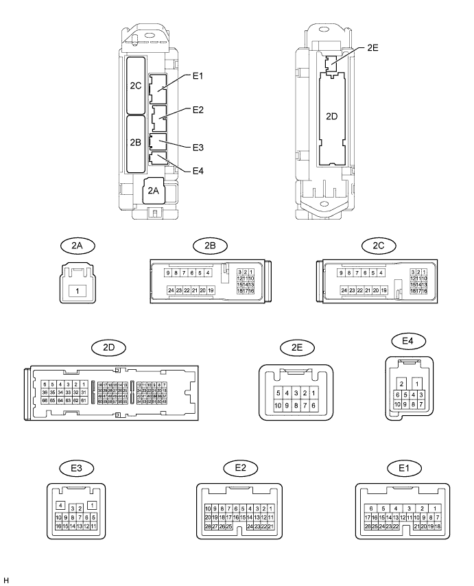
CHECK MAIN BODY ECU (COWL SIDE JUNCTION BLOCK LH)
-
Disconnect the E1, E2, E3, 2A, 2B and 2D ECU connectors.
-
Measure the resistance and voltage of the wire harness side connectors.
Terminal No. (Symbol) Wiring Color Terminal Description Condition Specified Condition 2D-62 (GND2) - Body ground W-B - Body ground Ground Always Below 1 Ω E3-1 (GND3) - Body ground BR - Body ground Ground Always Below 1 Ω 2A-1 (ALTB) - Body ground B - Body ground ALTB power supply Always 11 to 14 V 2B-20 (BATB) - Body ground L - Body ground BATB power supply Always 11 to 14 V E1-6 (AM1) - Body ground W - Body ground AM1 power supply Always 11 to 14 V E2-1 (AM2) - Body ground W - Body ground AM2 power supply Always 11 to 14 V 2A-1 (IG) - Body ground G - Body ground IG1 signal Engine switch on (IG) 11 to 14 V Engine switch off Below 1 V 2D-8 (ACC) - Body ground GR - Body ground ACC signal Engine switch on (ACC) 11 to 14 V Engine switch off Below 1 V E3-5 (CANH) - Body ground SB - Body ground CAN communication line Always 10 kΩ or higher E3-6 (CANL) - Body ground B - Body ground CAN communication line Always 10 kΩ or higher E3-15 (CANN) - Body ground R - Body ground CAN communication line Always 10 kΩ or higher E3-16 (CANP) - Body ground GR - Body ground CAN communication line Always 10 kΩ or higher 2D-20 (LIN1) - Body ground GR - Body ground LIN communication line Always 10 kΩ or higher E3-10 (LIN2) - Body ground G - Body ground LIN communication line Always 10 kΩ or higher
-
If the result is not as specified, the wire harness side may have a malfunction.
-
-
Reconnect the E1, E2, E3, 2A, 2B and 2D ECU connectors.
-
Measure the voltage of the connectors.
Terminal No. (Symbol) Wiring Color Terminal Description Condition Specified Condition E1-24 (DCTY) - Body ground L - Body ground*1
Y - Body ground*2
Driver side door courtesy switch input Driver side door open Below 1 V Engine switch off, and driver side door courtesy switch off Pulse generation (see waveform 1 or 2) E2-21 (PCTY) - Body ground Y - Body ground*1
L - Body ground*2
Front passenger side door courtesy switch input Front passenger side door open Below 1 V Engine switch off, and passenger side door courtesy switch off Pulse generation (see waveform 3 or 4) 2C-2 (LCTY) - Body ground W - Body ground Rear door LH courtesy light switch input Rear door LH open Below 1 V Engine switch off, and rear LH side door courtesy switch off Pulse generation (see waveform 5 or 6) E2-7 (RCTY) - Body ground G - Body ground Rear door RH courtesy light switch input Rear door RH open Below 1 V Engine switch off, and rear RH side door courtesy switch off Pulse generation (see waveform 7 or 8) E2-25 (BCTY) - Body ground W - Body ground Back door courtesy light switch input Back door open Below 1 V Engine switch off, and back door closed Pulse generation (see waveform 9 or 10) E3-7 (HZSW) - Body ground BE - Body ground Hazard warning light signal Answer-back on Below 1 V Answer-back off 11 to 14 V E1-26 (BDSU) - Body ground L - Body ground Back door opener switch input Back door lock opener switch off Below 1 V Back door lock opener switch on Pulse generation (see waveform 11 or 12) Tip:
-
*1: for LHD
-
*2: for RHD
If the result is not as specified, the ECU may have a malfunction.
-
-
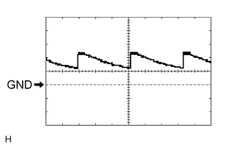
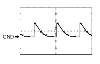
Using an oscilloscope, check waveform 1.
Table 1. Waveform 1 (Reference) Item Content Terminal No. (Symbol) E1-24 (DCTY) - Body ground Tool Setting 5 V/DIV., 20 ms/DIV. Condition Engine switch off, and driver side door courtesy switch off -
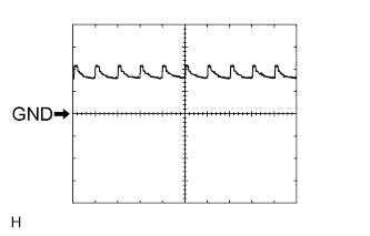
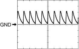
Using an oscilloscope, check waveform 2.
Table 2. Waveform 2 (Reference) Item Content Terminal No. (Symbol) E1-24 (DCTY) - Body ground Tool Setting 5 V/DIV., 20 ms/DIV. Condition Engine switch off, and driver side door courtesy switch off -
Using an oscilloscope, check waveform 3.
Table 3. Waveform 3 (Reference) Item Content Terminal No. (Symbol) E2-21 (PCTY) - Body ground Tool Setting 5 V/DIV., 20 ms/DIV. Condition Engine switch off, and passenger side door courtesy switch off -
Using an oscilloscope, check waveform 4.
Table 4. Waveform 4 (Reference) Item Content Terminal No. (Symbol) E2-21 (PCTY) - Body ground Tool Setting 5 V/DIV., 20 ms/DIV. Condition Engine switch off, and passenger side door courtesy switch off -
Using an oscilloscope, check waveform 5.
Table 5. Waveform 5 (Reference) Item Content Terminal No. (Symbol) 2C-2 (LCTY) - Body ground Tool Setting 5 V/DIV., 20 ms/DIV. Condition Engine switch off, and rear LH side door courtesy switch off -
Using an oscilloscope, check waveform 6.
Table 6. Waveform 6 (Reference) Item Content Terminal No. (Symbol) 2C-2 (LCTY) - Body ground Tool Setting 5 V/DIV., 20 ms/DIV. Condition Engine switch off, and rear LH side door courtesy switch off -
Using an oscilloscope, check waveform 7.
Table 7. Waveform 7 (Reference) Item Content Terminal No. (Symbol) E2-7 (RCTY) - Body ground Tool Setting 5 V/DIV., 20 ms/DIV. Condition Engine switch off, and rear RH side door courtesy switch off -
Using an oscilloscope, check waveform 8.
Table 8. Waveform 8 (Reference) Item Content Terminal No. (Symbol) E2-7 (RCTY) - Body ground Tool Setting 5 V/DIV., 20 ms/DIV. Condition Engine switch off, and rear RH side door courtesy switch off -
Using an oscilloscope, check waveform 9.
Table 9. Waveform 9 (Reference) Item Content Terminal No. (Symbol) E2-25 (BCTY) - Body ground Tool Setting 5 V/DIV., 20 ms/DIV. Condition Engine switch off, and back door closed -
Using an oscilloscope, check waveform 10.
Table 10. Waveform 10 (Reference) Item Content Terminal No. (Symbol) E2-25 (BCTY) - Body ground Tool Setting 5 V/DIV., 20 ms/DIV. Condition Engine switch off, and back door closed -
Using an oscilloscope, check waveform 11.
Table 11. Waveform 11 (Reference) Item Content Terminal No. (Symbol) E1-26 (BDSU) - Body ground Tool Setting 5 V/DIV., 20 ms/DIV. Condition Engine switch off, all doors closed and Back door lock opener switch on -
Using an oscilloscope, check waveform 12.
Table 12. Waveform 12 (Reference) Item Content Terminal No. (Symbol) E1-26 (BDSU) - Body ground Tool Setting 5 V/DIV., 20 ms/DIV. Condition Engine switch off, all doors closed and Back door lock opener switch on
-
-
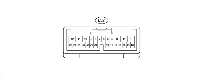
CHECK POWER BACK DOOR UNIT (w/ Power Back Door)
-
Disconnect the L52 unit connector.
-
Measure the voltage and resistance according to the value(s) in the table below.
Terminal No. (Symbol) Wiring Color Terminal Description Condition Specified Condition L52-10 (ECUB) - Body ground R - Body ground ECUB power supply Always 11 to 14 V L52-11 (GND) - Body ground W-B - Body ground Body ground Always Below 1 Ω If the result is not as specified, there may be a malfunction on the wire harness side.
-
Reconnect the L52 unit connector.
-
Measure the voltage according to the value(s) in the table below.
Terminal No. (Symbol) Wiring Color Terminal Description Condition Specified Condition L52-2 (DC+) - L52-1 (DC-) R - B Power back door lock motor circuit Back door lock motor is operating 11 to 14 V L52-2 (DC+) - L52-1 (DC-) R - B Power back door lock motor circuit Back door lock motor is stopped Below 1 V If the result is not as specified, the ECU may have a malfunction.
-