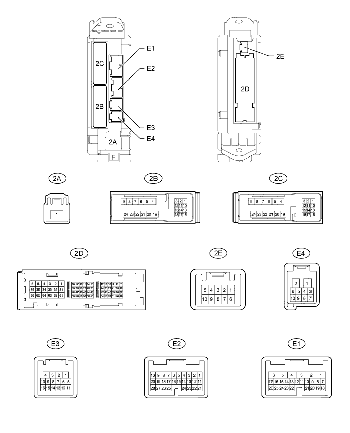
ENTRY AND START SYSTEM (for Start Function) TERMINALS OF ECU

-
CHECK MAIN BODY ECU (COWL SIDE JUNCTION BLOCK LH)
-
Disconnect the E1, E2 and 2D main body ECU connectors.
-
Measure the voltage and resistance according to the value(s) in the table below.
Terminal No. (Symbol) Wiring Color Terminal Description Condition Specified Condition E1-6 (AM1) - Body ground W - Body ground +B power supply Always 11 to 14 V E2-1 (AM2) - Body ground W - Body ground +B power supply Always 11 to 14 V E1-17 (SSW1) - Body ground B - Body ground Engine switch 1 input Engine switch pushed Below 1 Ω E1-17 (SSW1) - Body ground B - Body ground Engine switch 1 input Engine switch not pushed 10 kΩ or higher E1-16 (SSW2) - Body ground B - Body ground Engine switch 2 input Engine switch pushed Below 1 Ω E1-16 (SSW2) - Body ground B - Body ground Engine switch 2 input Engine switch not pushed 10 kΩ or higher 2D-62 (GND2) - Body ground W-B - Body ground Ground Always Below 1 Ω 2D-20 (LIN1) - Body ground GR - Body ground LIN line Always 10 kΩ or higher If the result is not as specified, there may be a malfunction on the wire harness side.
-
Reconnect the E1, E2 and 2D main body ECU connectors.
-
Measure the voltage according to the value(s) in the table below.
Terminal No. (Symbol) Wiring Color Terminal Description Condition Specified Condition E1-22 (ACCD) - 2D-62 (GND2) P - W-B ACC relay drive signal Engine switch on (ACC) 11 to 14 V E1-22 (ACCD) - 2D-62 (GND2) P - W-B ACC relay drive signal Engine switch off Below 1 V E1-3 (IG1D) - 2D-62 (GND2) G - W-B IG1 No. 3 relay drive signal Engine switch on (IG) 11 to 14 V E1-3 (IG1D) - 2D-62 (GND2) G - W-B IG1 No. 3 relay drive signal Engine switch on (ACC) Below 1 V E2-11 (IG2D) - 2D-62 (GND2) B - W-B Integration relay (IG2 relay) drive signal Engine switch on (IG) 11 to 14 V E2-11 (IG2D) - 2D-62 (GND2) B - W-B Integration relay (IG2 relay) drive signal Engine switch on (ACC) Below 1 V E1-19 (SLR+) - 2D-62 (GND2) G - W-B Steering lock power supply Steering lock motor operating Below 1 V E1-19 (SLR+) - 2D-62 (GND2) G - W-B Steering lock power supply Steering lock motor not operating 11 to 14 V E1-8 (STR) - 2D-62 (GND2) L - W-B Park/neutral position switch signal*1
Clutch pedal switch signal*2
Engine switch on (IG), shift lever not in P or N → P or N*1
Engine switch on (IG), Clutch pedal switch released → Depressed*2
Below 2 V → Pulse generation*3 E1-18 (SLP) - 2D-62 (GND2) SB - W-B Steering lock actuator position signal Steering lock locked 11 to 14 V E1-18 (SLP) - 2D-62 (GND2) SB - W-B Steering lock actuator position signal Steering lock released Below 1 V E3-9 (SPD) - 2D-62 (GND2) V - W-B Speed signal from combination meter Engine switch on (IG), driving wheel rotating slowly Pulse generation
(see waveform 1)
E3-8 (TACH) - 2D-62 (GND2) W - W-B Tachometer signal Engine running Pulse generation
(see waveform 2)
E4-2 (P) - 2D-62 (GND2)*1 L - W-B Shift lock signal Shift lever in P Pulse generation
(see waveform 3)
E4-2 (P) - 2D-62 (GND2)*1 L - W-B Shift lock signal Shift lever not in P Below 1 V E4-4 (STSW) - 2D-62 (GND2) R - W-B Starter activation request signal Brake pedal depressed, engine switch depressed*1
Clutch pedal depressed, engine switch depressed*2
11 to 14 V E1-15 (INDS) - 2D-62 (GND2) W - W-B Vehicle condition signal Brake pedal released with shift lever in P or N, engine switch off, on (ACC), or on (IG)*1
Clutch pedal released, engine switch off, on (ACC), or on (IG)*2
9 to 14 V E1-14 (INDW) - 2D-62 (GND2) W - W-B Vehicle condition signal Brake pedal released with shift lever in P or N, engine switch off, on (ACC), or on (IG)*1
Clutch pedal released, engine switch off, on (ACC), or on (IG)*2
9 to 14 V E1-25 (SWIL) - 2D-62 (GND2) R - W-B Illumination signal Light control switch tail or head 11 to 14 V 2B-22 (STP) - 2D-62 (GND2) R - W-B Stop light switch signal Brake pedal depressed 11 to 14 V 2B-22 (STP) - 2D-62 (GND2) R - W-B Stop light switch signal Brake pedal released Below 1 V Tech Tips
*1: for A/T
*2: for M/T
*3: Remove the ST CUT relay before measuring the voltage.
If the result is not as specified, the ECU may have a malfunction.
-
Using an oscilloscope, check the signal waveform of the ECU.
-
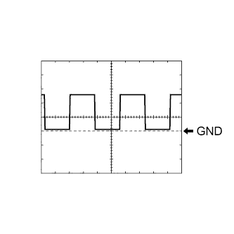
Waveform 1
Reference Terminal No. (Symbol) Tool Setting Condition E3-9 (SPD) - 2D-62 (GND2) 5 V/DIV., 100 msec./DIV. Driving at approx. 20 km/h (12 mph) Tech Tips
As the vehicle speed increases, the wavelength shortens.
-
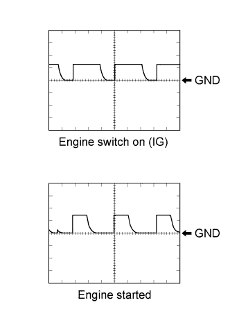
Waveform 2
Reference Terminal No. (Symbol) Tool Setting Condition E3-8 (TACH) - 2D-62 (GND2) 10 V/DIV., 10 msec./DIV. Engine switch on (IG) or engine started -
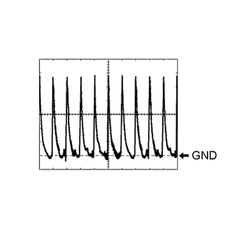
Waveform 3
Reference Terminal No. (Symbol) Tool Setting Condition E4-2 (P) - 2D-62 (GND2) 2 V/DIV., 20 msec./DIV. Shift lever in P
-
-
-
CHECK CERTIFICATION ECU (SMART KEY ECU ASSEMBLY)

-
Disconnect the E29 certification ECU (smart key ECU assembly) connector.
-
Measure the voltage and resistance according to the value(s) in the table below.
Terminal No. (Symbol) Wiring Color Terminal Description Condition Specified Condition E29-1 (+B) - Body ground B - Body ground +B power supply Always 11 to 14 V E29-10 (LIN) - Body ground GR - Body ground LIN line Always 10 kΩ or higher E29-17 (E) - Body ground W-B - Body ground Ground Always Below 1 Ω If the result is not as specified, there may be a malfunction on the wire harness side.
-
Reconnect the E29 certification ECU (smart key ECU assembly) connector.
-
Measure the voltage according to the value(s) in the table below.
Terminal No. (Symbol) Wiring Color Terminal Description Condition Specified Condition E29-18 (IG) - Body ground B - Body ground Ignition power supply Engine switch on (IG) 11 to 14 V E29-18 (IG) - Body ground B - Body ground Ignition power supply Engine switch off Below 1 V If the result is not as specified, the certification ECU (smart key ECU assembly) may have a malfunction.
-
-
CHECK ECM
-
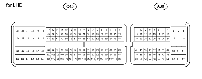
for LHD:
Disconnect the A38 and C45 ECM connectors.
-
Measure the voltage and resistance according to the value(s) in the table below.
Terminal No. (Symbol) Wiring Color Terminal Description Condition Specified Condition A38-1 (BATT) - C45-81 (E1)*1, *2, *3
A38-20 (BATT) - C45-81 (E1)*4, *5
L - BR*1, *2, *4, *5
L - W-B*3
Battery (for measuring battery voltage and for ECM memory) Always 11 to 14 V A38-3 (+B) - C45-81 (E1)*1, *2, *3
A38-2 (+B) - C45-81 (E1)*4, *5
B - BR*1, *2, *4, *5
B - W-B*3
Power source of ECM Engine switch on (IG) 11 to 14 V A38-28 (IGSW) - C45-81 (E1) B - BR*1, *2, *4, *5
B - W-B*3
Engine switch signal Always 11 to 14 V C45-81 (E1) - Body ground BR - Body ground*1, *2, *4, *5
W-B - Body ground*3
Ground Always Below 1 Ω C45-43 (E01) - Body ground*1, *2, *3
C45-22 (E01) - Body ground*4, *5
W-B - Body ground Ground Always Below 1 Ω C45-42 (E02) - Body ground*1, *2, *3
C45-21 (E02) - Body ground*4, *5
BR - Body ground Ground Always Below 1 Ω C45-46 (E03) - Body ground*1, *2, *3 W-B - Body ground Ground Always Below 1 Ω C45-23 (E04) - Body ground*1, *2, *3
C45-44 (E04) - Body ground*5
W-B - Body ground*1, *2, *3
BR - Body ground*5
Ground Always Below 1 Ω C45-21 (E05) - Body ground*1, *2, *3
C45-23 (E05) - Body ground*5
W-B - Body ground Ground Always Below 1 Ω Tech Tips
*1: for 1UR-FE
*2: for 1GR-FE
*3: for 3UR-FE
*4: for 1VD-FTV w/o DPF
*5: for 1VD-FTV w/DPF
If the result is not as specified, there may be a malfunction on the wire harness side.
-
Reconnect the ECM connectors.
-
Measure the voltage according to the value(s) in the table below.
Terminal No. (Symbol) Wiring Color Terminal Description Condition Specified Condition A38-46 (STA) - C45-81 (E1)*1, *2, *3, *6
A38-48 (STA) - C45-81 (E1)*4, *5
R - BR*1, *2, *4, *5
R - W-B*3
R-B - BR*6
ST relay operation signal Cranking 5.5 V or more A38-14 (STSW) - C45-81 (E1)*1, *2, *3, *4, *6
A38-47 (STSW) - C45-81 (E1)*5
R - BR*1, *2, *4, *5, *6
R - W-B*3
Starter activation request signal Brake pedal depressed, engine switch on (IG) Output voltage at terminal AM1 or AM2 is -2 V or more A38-41 (ACCR) - C45-81 (E1)*1, *2, *3, *6
A38-13 (ACCR) - C45-81 (E1)*4
A38-22 (ACCR) - C45-81 (E1)*5
L-Y - BR*1, *2, *4, *5, *6
L-Y - W-B*3
ACC relay cut signal
(output)
Engine switch on (IG) → Cranking 11 to 14 V → Below 1 V A38-15 (TACH) - C45-81 (E1) W - BR*1, *2, *4, *5
W - W-B*3
W-G - BR*6
Engine speed signal
(output)
Idling Pulse generation
(see waveform 1)
C45-16 (STAR) - C45-81 (E1)*1, *2, *3, *6
C45-51 (STAR) - C45-81 (E1)*4
C45-52 (STAR) - C45-81 (E1)*5
L - BR*1, *2, *4, *5, *6
L - W-B*3
ST relay drive signal Cranking 11 to 14 V Tech Tips
*1: for 1UR-FE (except URJ202L-GNTEKC)
*2: for 1GR-FE (except GRJ200L-GNANKC)
*3: for 3UR-FE
*4: for 1VD-FTV w/o DPF
*5: for 1VD-FTV w/ DPF
*6: for GRJ200L-GNANKC, URJ202L-GNTEKC
If the result is not as specified, the ECM may have a malfunction.
-
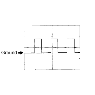
Using an oscilloscope, check the signal waveform of the ECM.
Reference Terminal No. (Symbol) Tool Setting Condition A38-15 (TACH) - C45-81 (E1) 5 V/DIV., 10 ms./DIV. Engine idling Tech Tips
As the engine speed increases, the wavelength shortens.
-
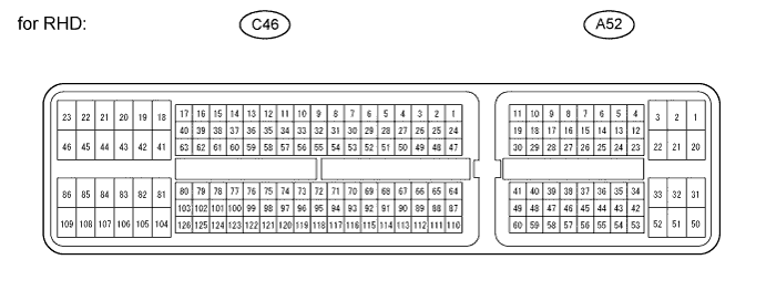
for RHD:
Disconnect the A52 and C46 ECM connectors.
-
Measure the voltage and resistance according to the value(s) in the table below.
Terminal No. (Symbol) Wiring Color Terminal Description Condition Specified Condition A52-1 (BATT) - C46-81 (E1)*1. *2
A52-20 (BATT) - C46-81 (E1)*3, *4
L - BR Battery (for measuring battery voltage and for ECM memory) Always 11 to 14 V A52-3 (+B) - C46-81 (E1)*1, *2
A52-2 (+B) - C46-81 (E1)*3, *4
B - BR Power source of ECM Engine switch on (IG) 11 to 14 V A52-28 (IGSW) - C46-81 (E1) B - BR Engine switch signal Always 11 to 14 V C46-81 (E1) - Body ground BR - Body ground Ground Always Below 1 Ω C46-43 (E01) - Body ground*1, *2
C46-22 (E01) - Body ground*3, *4
W-B - Body ground Ground Always Below 1 Ω C46-42 (E02) - Body ground*1, *2
C46-21 (E02) - Body ground*3, *4
BR - Body ground Ground Always Below 1 Ω C46-46 (E03) - Body ground*1, *2 W-B - Body ground Ground Always Below 1 Ω C46-23 (E04) - Body ground*1, *2
C46-44 (E04) - Body ground*4
W-B - Body ground*1, *2
BR - Body ground*4
Ground Always Below 1 Ω C46-21 (E05) - Body ground*1, *2
C46-23 (E05) - Body ground*4
W-B - Body ground Ground Always Below 1 Ω Tech Tips
*1: for 1UR-FE
*2: for 1GR-FE
*3: for 1VD-FTV w/o DPF
*4: for 1VD-FTV w/ DPF
If the result is not as specified, there may be a malfunction on the wire harness side.
-
Reconnect the ECM connectors.
-
Measure the voltage according to the value(s) in the table below.
Terminal No. (Symbol) Wiring Color Terminal Description Condition Specified Condition A52-46 (STA) - C46-81 (E1)*1, *2, *5
A52-48 (STA) - C46-81 (E1)*3, *4
R - BR*1, *2, *3, *4
R-B - BR*5
ST relay operation signal Cranking 5.5 V or more A52-14 (STSW) - C46-81 (E1)*1, *2, *3, *5
A52-47 (STSW) - C46-81 (E1)*4
R - BR Starter activation request signal Brake pedal depressed, engine switch on (IG) Output voltage at terminal AM1 or AM2 is -2 V or more A52-41 (ACCR) - C46-81 (E1)*1, *2, *5
A52-13 (ACCR) - C46-81 (E1)*3
A52-22 (ACCR) - C46-81 (E1)*4
L-Y - BR ACC relay cut signal
(output)
Engine switch on (IG) → Cranking 11 to 14 V → Below 1 V A52-15 (TACH) - C46-81 (E1) W - BR*1, *2, *3, *4
W-G - BR*5
Engine speed signal
(output)
Idling Pulse generation
(see waveform 1)
C46-16 (STAR) - C46-81 (E1)*1, *2, *5
C46-51 (STAR) - C46-81 (E1)*3
C46-52 (STAR) - C46-81 (E1)*4
L - BR ST relay drive signal Cranking 11 to 14 V Tech Tips
*1: for 1UR-FE (except URJ202L-GNTEKC)
*2: for 1GR-FE (except GRJ200L-GNANKC)
*3: for 1VD-FTV w/o DPF
*4: for 1VD-FTV w/ DPF
*5: for GRJ200L-GNANKC, URJ202L-GNTEKC
If the result is not as specified, the ECM may have a malfunction.
-
Using an oscilloscope, check the signal waveform of the ECM.
Reference Terminal No. (Symbol) Tool Setting Condition A52-15 (TACH) - C46-81 (E1) 5 V/DIV., 10 ms./DIV. Engine idling Tech Tips
As the engine speed increases, the wavelength shortens.
-
-
CHECK STEERING LOCK ECU

-
Disconnect the E26 steering lock ECU connector.
-
Measure the voltage and resistance according to the value(s) in the table below.
Terminal No. (Symbol) Wiring Color Terminal Description Condition Specified Condition E26-7 (B) - Body ground R - Body ground +B power supply Always 11 to 14 V E26-6 (IG2) - Body ground B - Body ground Ignition power supply Engine switch on (IG) 11 to 14 V E26-6 (IG2) - Body ground B - Body ground Ignition power supply Engine switch off Below 1 V E26-1 (GND) - Body ground W-B - Body ground Ground Always Below 1 Ω E26-2 (SGND) - Body ground BR - Body ground Ground Always Below 1 Ω If the result is not as specified, there may be a malfunction on the wire harness side.
-
Reconnect the E26 steering lock ECU connector.
-
Measure the voltage according to the value(s) in the table below.
Terminal No. (Symbol) Wiring Color Terminal Description Condition Specified Condition E26-4 (SLP1) - E26-1 (GND) SB - W-B Steering lock actuator position signal Steering locked 11 to 14 V E26-4 (SLP1) - E26-1 (GND) SB - W-B Steering lock actuator position signal Steering released Below 1 V If the result is not as specified, the ECU may have a malfunction.
-