REAR DOOR LOCK INSTALLATION

Tech Tips
-
Use the same procedures for the LH side and RH side.
-
The procedures listed below are for the LH side.
-
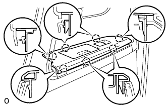
INSTALL REAR DOOR INSIDE LOCKING CABLE ASSEMBLY LH
-
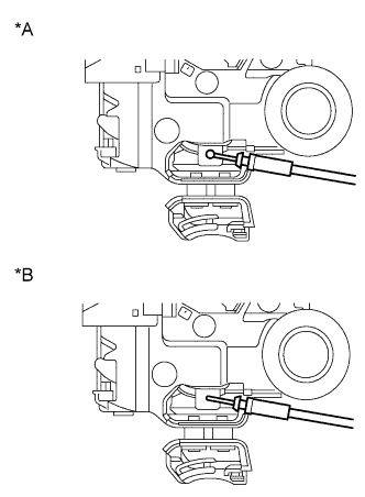
Text in Illustration *A w/o Double Lock *B w/ Double Lock Install the rear door inside locking cable assembly LH.
-
Attach the 3 claws.
-
-
INSTALL REAR DOOR LOCK REMOTE CONTROL CABLE ASSEMBLY LH
-
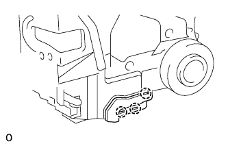
Install the rear door lock remote control cable assembly LH.
-
Attach the claw.
-
-
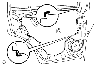
INSTALL REAR DOOR LOCK ASSEMBLY LH
-
Apply MP grease to the sliding parts of the rear door lock assembly.
-
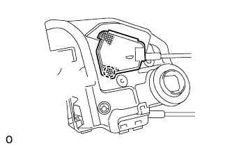
Insert the rear door lock assembly to the rear door outside handle release plate, and set it to the rear door panel.
-
Make sure that the rear door outside handle frame release plate is securely connected to the rear door lock assembly.
-
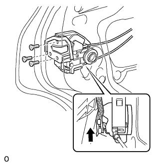
Using a T30 ''TORX'' wrench, the 3 screws.
- Torque:
- 5.0 N*m { 51 kgf*cm, 44 in.*lbf }
-
-
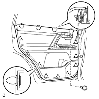
INSTALL REAR DOOR SERVICE HOLE COVER LH
-
Apply butyl tape to the door.
-
Pass the rear door lock remote control cable assembly LH and rear door inside locking cable assembly LH through a new rear door service hole cover LH.
Note
-
When installing the rear door service hole cover LH, pull the links and connectors through the rear door service hole cover LH.
-
There should be no wrinkles or folds after attaching the rear door service hole cover LH.
-
After attaching the rear door service hole cover LH, check the sealing quality.
-
-
Connect the 2 connectors.
-
Attach the 6 clamps.
-
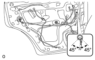
Install the bolt as shown in the illustration.
- Torque:
- 8.4 N*m { 86 kgf*cm, 74 in.*lbf }
-
-
INSTALL COURTESY LIGHT ASSEMBLY (w/ Courtesy Light)
-
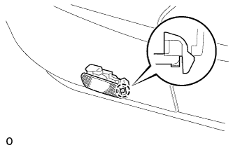
Connect the connector.
-
Attach the claw of the courtesy light to the rear door trim.
-
-
INSTALL REAR DOOR TRIM BOARD SUB-ASSEMBLY LH
-
Connect the connector.
-
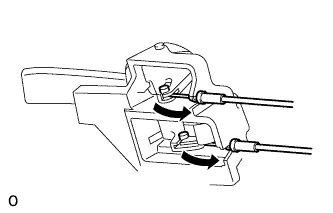
Connect the rear door lock remote control cable assembly LH and rear door inside locking cable assembly LH to the rear door inside handle sub-assembly LH.
-
Attach the 4 claws and 9 clips to install the rear door trim board sub-assembly LH.
-
Install the 3 screws.
-
-
INSTALL ASSIST GRIP COVER LH
-
Attach the 9 claws to install the assist grip cover LH to the rear door trim board sub-assembly LH.
-
-
INSTALL REAR DOOR INSIDE HANDLE BEZEL LH
-
Install the rear door inside handle bezel LH to the trim board with the 6 screws.
-
-
INSTALL REAR DOOR ARMREST BASE PANEL ASSEMBLY LH
-
Connect the connector.
-
Attach the 7 claws to install the armrest base panel.
-
-
CONNECT CABLE TO NEGATIVE BATTERY TERMINAL
Note
When disconnecting the cable, some systems need to be initialized after the cable is reconnected Click here.