UNLOCK WARNING SWITCH INSTALLATION

-
INSTALL UNLOCK WARNING SWITCH ASSEMBLY
-
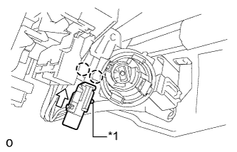
Text in Illustration *1 Pin While pushing the pin, slide the warning switch to install it.
-
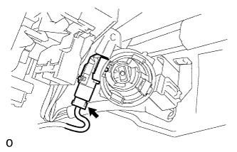
Connect the unlock warning switch connector.
-
-
INSTALL IGNITION SWITCH LOCK CYLINDER ASSEMBLY
-
Turn the ignition switch lock cylinder assembly to ACC.
-
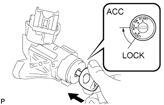
Insert the ignition switch lock cylinder assembly into the steering column upper bracket assembly to install it.
-
Check that the ignition switch lock cylinder assembly is securely fixed in place.
-
-
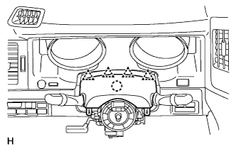
INSTALL TRANSPONDER KEY AMPLIFIER
-
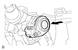
Connect the transponder key amplifier connector.
-
Align the claw of the transponder key amplifier with the upper bracket.
-
Push in the transponder key amplifier and install it to the upper bracket.
Note
Do not push in the transponder key amplifier with excessive force as it may be damaged.
-
-
INSTALL UPPER STEERING COLUMN COVER
-
Attach the claw to install the upper steering column cover.
-
Attach the 4 clips to install the upper steering column cover onto the instrument cluster finish panel.
-
-
INSTALL LOWER STEERING COLUMN COVER
-
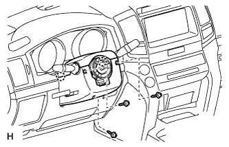
Attach the 2 claws to install the lower steering column cover.
Note
Do not damage the tilt and telescopic switch.
-
Install the 3 screws.
- Torque:
- 2.0 N*m { 20 kgf*cm, 18 in.*lbf }
-
-
CONNECT CABLE TO NEGATIVE BATTERY TERMINAL
Note
When disconnecting the cable, some systems need to be initialized after the cable is reconnected Click here.