LIN COMMUNICATION SYSTEM Rear Heater Control Panel LIN Communication Malfunction
DESCRIPTION
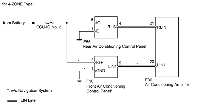
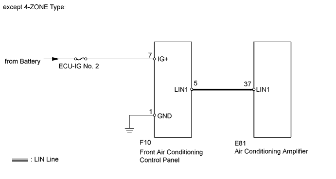
The LIN communication of the components related to the rear air conditioning occurs between the air conditioning amplifier (A/C ECU), rear air conditioning control panel and front air conditioning control panel.
WIRING DIAGRAM
INSPECTION PROCEDURE
Note
When using the intelligent tester with the ignition switch off to troubleshoot:
Connect the intelligent tester to the vehicle, and turn a courtesy switch on and off at 1.5 second intervals until communication between the intelligent tester and vehicle begins.
PROCEDURE
-
CHECK AIR CONDITIONING TYPE
-
Check air conditioning type.
Result Result Proceed to for 4-ZONE Type A except 4-ZONE Type B
B 
CHECK HARNESS AND CONNECTOR (A/C ECU - FRONT AIR CONDITIONING CONTROL PANEL) Click here
A 
-
-
CHECK HARNESS AND CONNECTOR (A/C ECU - REAR AIR CONDITIONING CONTROL PANEL AND FRONT AIR CONDITIONING CONTROL PANEL*)
Tech Tips
*: w/o Navigation System
-
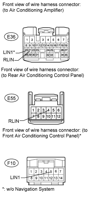
Disconnect the E36 amplifier connector.
-
Disconnect the F10* and E55 panel connector.
-
Measure the resistance and voltage according to the value(s) in the tables below.
Standard Resistance Tester Connection Condition Specified Condition E36-21 (RLIN) - E55-4 (RLIN) Always Below 1 Ω E36-20 (LIN1) - F10-5 (LIN1)* Always Below 1 Ω E36-21 (RLIN) - Body ground Always 10 kΩ or higher E36-20 (LIN1) - Body ground* Always 10 kΩ or higher Standard Voltage Tester Connection Condition Specified Condition E36-21 (RLIN) - Body ground Always Below 1 V E36-20 (LIN1) - Body ground* Always Below 1 V
NG 
REPAIR OR REPLACE HARNESS OR CONNECTOR
OK
-
-
CHECK AIR CONDITIONING CONTROL PANEL (BATTERY VOLTAGE AND BODY GROUND)
-
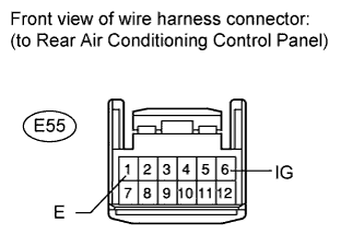
Disconnect the E55 panel connector.
-
Measure the resistance and voltage according to the value(s) in the tables below.
Standard Resistance Tester Connection Condition Specified Condition E55-1 (E) - Body ground Always Below 1 Ω Standard Voltage Tester Connection Switch Condition Specified Condition E55-6 (IG) - Body ground Ignition switch ON 11 to 14 V
NG
REPAIR OR REPLACE HARNESS OR CONNECTOR
OK
-
-
CHECK REAR AIR CONDITIONING CONTROL PANEL
-
Temporarily replace the rear air conditioning control panel with a new or normally functioning one Click here.
-
Check that the rear air conditioning function is normal.
OK Rear air conditioning function is normal. Result Result Proceed to OK A NG (w/ Navigation System) B NG (w/o Navigation System) (for LHD) C NG (w/o Navigation System) (for RHD) D
B
CHECK FRONT AIR CONDITIONING CONTROL PANEL Click here
C
REPLACE AIR CONDITIONING AMPLIFIER Click here
D
REPLACE AIR CONDITIONING AMPLIFIER Click here
A 
END (REAR AIR CONDITIONING CONTROL PANEL IS DEFECTIVE)
-
-
CHECK FRONT AIR CONDITIONING CONTROL PANEL
-
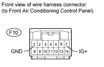
Disconnect the F10 panel connector.
-
Measure the resistance and voltage according to the value(s) in the tables below.
Standard Resistance Tester Connection Condition Specified Condition F10-1 (GND) - Body ground Always Below 1 Ω Standard Voltage Tester Connection Switch Condition Specified Condition F10-7 (IG+) - Body ground Ignition switch ON 11 to 14 V
NG
REPLACE FRONT AIR CONDITIONING PANEL Click here
OK
-
-
CHECK FRONT AIR CONDITIONING CONTROL PANEL
-
Temporarily replace the front air conditioning control panel with a new or normally functioning one Click here.
-
Check the that front air conditioning function is normal.
OK Front air conditioning function is normal. Result Result Proceed to OK A NG (for LHD) B NG (for RHD) C
B
REPLACE AIR CONDITIONING AMPLIFIER Click here
C
REPLACE FRONT AIR CONDITIONING CONTROL ASSEMBLY Click here
A
END (FRONT AIR CONDITIONING CONTROL PANEL IS DEFECTIVE)
-
-
CHECK HARNESS AND CONNECTOR (A/C ECU - FRONT AIR CONDITIONING CONTROL PANEL)
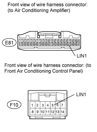
-
Disconnect the E81 amplifier connector.
-
Disconnect the F10 panel connector.
-
Measure the resistance and voltage according to the value(s) in the tables below.
Standard Resistance Tester Connection Condition Specified Condition E81-37 (LIN1) - F10-5 (LIN1) Always Below 1 Ω E81-37 (LIN1) - Body ground Always 10 kΩ or higher Standard Voltage Tester Connection Condition Specified Condition E81-37 (LIN1) - Body ground Always Below 1 V
NG
REPAIR OR REPLACE HARNESS OR CONNECTOR
OK
-
-
CHECK FRONT AIR CONDITIONING CONTROL ASSEMBLY (BATTERY VOLTAGE AND BODY GROUND)
-
Disconnect the F10 panel connector.
-
Measure the resistance and voltage according to the value(s) in the tables below.
Standard Resistance Tester Connection Condition Specified Condition F10-1 (GND) - Body ground Always Below 1 Ω Standard Voltage Tester Connection Switch Condition Specified Condition F10-7 (IG+) - Body ground Ignition switch ON 11 to 14 V
NG
REPLACE FRONT AIR CONDITIONING CONTROL ASSEMBLY Click here
OK
-
-
CHECK FRONT AIR CONDITIONING CONTROL ASSEMBLY
-
Temporarily replace the front air conditioning control panel with a new or normally functioning one Click here.
Check the that front air conditioning function is normal.
OK Front air conditioning function is normal. Result Result Proceed to OK A NG (for LHD) B NG (for RHD) C
B
REPLACE AIR CONDITIONING AMPLIFIER ASSEMBLY Click here
C
REPLACE AIR CONDITIONING AMPLIFIER ASSEMBLY Click here
A
END (FRONT AIR CONDITIONING CONTROL PANEL IS DEFECTIVE)
-