GENERATOR REMOVAL

-
REMOVE V-BANK COVER SUB-ASSEMBLY
-
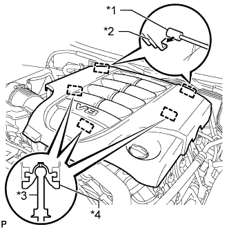
Text in Illustration *1 Bracket *2 Hook *3 Pin *4 Grommet Raise the front of the V-bank cover to detach the 3 pins. Then remove the 2 V-bank cover hooks from the bracket, and remove the V-bank cover.
-
-
PRECAUTION
Note
After turning the engine switch off, waiting time may be required before disconnecting the cable from the battery terminal. Therefore, make sure to read the disconnecting the cable from the battery terminal notice before proceeding with work Click here.
-
DISCONNECT CABLE FROM NEGATIVE BATTERY TERMINAL
Note
When disconnecting the cable, some systems need to be initialized after the cable is reconnected Click here.
-
REMOVE FRONT FENDER SPLASH SHIELD SUB-ASSEMBLY LH
-
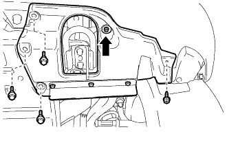
Remove the 3 bolts and screw.
-
Turn the clip indicated by the arrow in the illustration to remove the front fender splash shield sub-assembly LH.
-
-
REMOVE FRONT FENDER SPLASH SHIELD SUB-ASSEMBLY RH
-
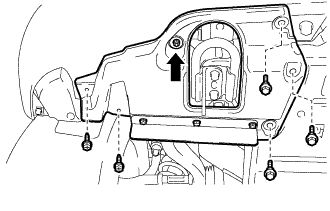
Remove the 3 bolts and 2 screws.
-
Turn the clip indicated by the arrow in the illustration to remove the front fender splash shield sub-assembly RH.
-
-
REMOVE NO. 1 ENGINE UNDER COVER SUB-ASSEMBLY
-
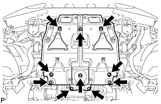
Remove the 10 bolts and No. 1 engine under cover.
-
-
REMOVE FAN AND GENERATOR V BELT
-
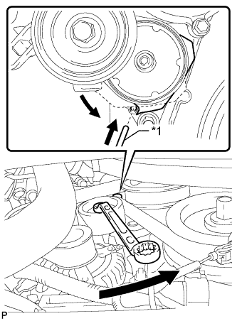
Text in Illustration *1 Bar While turning the belt tensioner counterclockwise, align the service hole for the belt tensioner and the belt tensioner fixing position, and then insert a bar of 5 mm (0.197 in.) into the service hole to fix the belt tensioner in place.
Tech Tips
The pulley bolt for the belt tensioner has a left-hand thread.
-
Remove the V belt.
-
-
REMOVE FRONT FENDER APRON SEAL FRONT RH
-
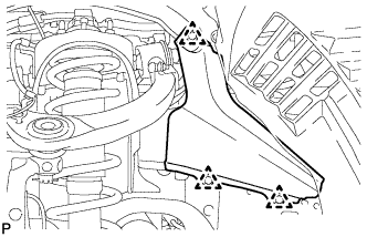
Using a clip remover, remove the 3 clips and fender apron seal.
-
-
REMOVE AIR CLEANER HOSE ASSEMBLY
-
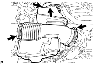
Disconnect the vacuum hose and No. 2 ventilation hose.
-
Loosen the 2 hose clamps.
-
Remove the air cleaner hose.
-
-
REMOVE AIR CLEANER ASSEMBLY
-
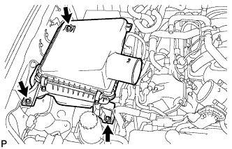
Remove the 3 bolts and air cleaner.
-
-
DISCONNECT VANE PUMP ASSEMBLY
-
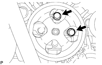
Remove the 2 bolts and disconnect the vane pump.
-
-
DISCONNECT OIL COOLER PIPE ASSEMBLY
-
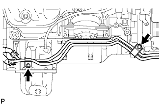
Remove the 2 bolts and disconnect the oil cooler pipe.
-
-
REMOVE GENERATOR ASSEMBLY
-
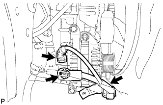
Disconnect the generator connector.
-
Open the terminal cap.
-
Remove the nut and disconnect the generator wire.
-
Remove the bolt and disconnect the wire harness bracket from the generator.
-
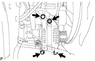
Remove the 3 bolts, nut and generator.
-
Remove the stud bolt.
-