GENERATOR (for 130 A Type) INSTALLATION

-
INSTALL GENERATOR ASSEMBLY
-
Install the generator bracket to the generator with the bolt.
- Torque:
- 20 N*m { 204 kgf*cm, 15 ft.*lbf }
-
Install the generator with the 2 bolts.
- Torque:
- 43 N*m { 438 kgf*cm, 32 ft.*lbf }
-
Connect the generator bracket with the bolt.
- Torque:
- 20 N*m { 204 kgf*cm, 15 ft.*lbf }
-
Connect the wire harness clamp bracket with the bolt.
- Torque:
- 8.0 N*m { 82 kgf*cm, 71 in.*lbf }
-
Connect the generator wire to terminal B with the nut.
- Torque:
- 9.8 N*m { 100 kgf*cm, 87 in.*lbf }
-
Close the terminal cap.
-
Connect the generator connector.
-
-
INSTALL FRONT FENDER APRON TRIM PACKING B
-
w/ KDSS:
Install the front fender apron trim packing B with the 3 clips.
-
w/o KDSS:
Install the front fender apron trim packing B with the 4 clips.
-
-
INSTALL FAN AND GENERATOR V BELT
-
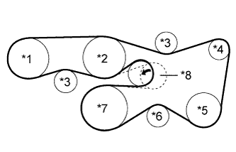
Text in Illustration *1 Vane Pump *2 Water Pump *3 No. 2 Idler *4 Generator *5 Cooler Compressor or Idler Pulley *6 No. 1 Idler *7 Crankshaft *8 V-ribbed Belt Tensioner Set the V belt onto every part.
-
While turning the belt tensioner counterclockwise, remove the pin.
Note
Make sure that the V belt is properly installed to each pulley.
-
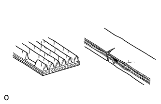
Check that the belt fits properly in the ribbed grooves.
Tech Tips
Make sure to check by hand that the belt has not slipped out of the grooves on the bottom of the pulley.
-
-
INSPECT FAN AND GENERATOR V BELT
-
Check the belt for wear, cracks or other signs of damage.
If any of the following defects is found, replace the fan and generator V belt.
-
The belt is cracked.
-
The belt is worn out to the extent that the cords are exposed.
-
The belt has chunks missing from the ribs.
-
-
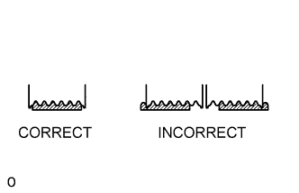
Check that the belt fits properly in the ribbed grooves.
Tech Tips
Check with your hand to confirm that the belt has not slipped out of the groove on the bottom of the pulley. If it has slipped out, replace the fan and generator V belt. Install a new fan and generator V belt correctly.
-
-
INSTALL NO. 1 ENGINE UNDER COVER SUB-ASSEMBLY
-
Install the No. 1 engine under cover with the 10 bolts.
- Torque:
- 29 N*m { 296 kgf*cm, 21 ft.*lbf }
-
-
INSTALL FRONT FENDER SPLASH SHIELD SUB-ASSEMBLY LH
-
Push in the clip to install the front fender splash shield sub-assembly LH.
-
Install the 3 bolts and screw.
-
-
INSTALL FRONT FENDER SPLASH SHIELD SUB-ASSEMBLY RH
-
Push in the clip to install the front fender splash shield sub-assembly RH.
-
Install the 3 bolts and 2 screws.
-
-
INSTALL V-BANK COVER
-
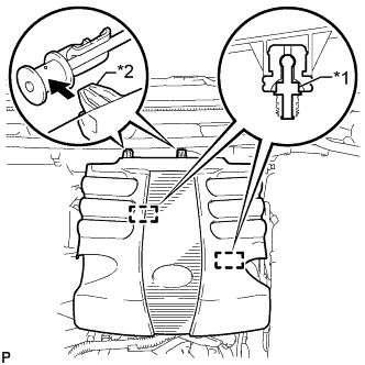
Text in Illustration *1 Pin *2 Hook Attach the 2 V-bank cover hooks to the bracket. Then align the 2 V-bank cover grommets with the 2 pins and press down on the V-bank cover to attach the pins.
-
-
CONNECT CABLE TO NEGATIVE BATTERY TERMINAL
Note
When disconnecting the cable, some systems need to be initialized after the cable is reconnected Click here.