DESCRIPTION
The No. 1 clearance warning buzzer sounds to alert the driver and the buzzed frequency changes depending on the distance to an obstacle.
INSPECTION PROCEDURE
PROCEDURE
- Click here
PERFORM ACTIVE TEST USING INTELLIGENT TESTER (NO. 1 CLEARANCE WARNING BUZZER)
-
Select the Active Test, use the intelligent tester to generate a control command, and then check that the buzzer operates (Click here).
Table 1. Clearance Sonar Tester Display Test Part Control Range Diagnostic Note Front Buzzer No. 1 clearance warning buzzer Operate or Stop - OK No. 1 clearance warning buzzer sounds. Table 2. Result Result Proceed to OK A NG (w/ Side Monitor System) B NG (w/o Side Monitor System) C
-
- Click here
CHECK HARNESS AND CONNECTOR (PARKING ASSIST ECU - NO. 1 CLEARANCE WARNING BUZZER)
-
Disconnect the F75 parking assist ECU connector.
-
Disconnect the E10 No. 1 clearance warning buzzer connector.
-
Measure the resistance according to the value(s) in the table below.
Standard Resistance Tester Connection Condition Specified Condition F75-7 (BBZ) - E10-1 (Z+) Always Below 1 Ω F75-6 (EF) - E10-2 (Z-) Always Below 1 Ω F75-7 (BBZ) - Body ground Always 10 kΩ or higher F75-6 (EF) - Body ground Always 10 kΩ or higher
- OKClick here
- NGClick here
-
- Click here
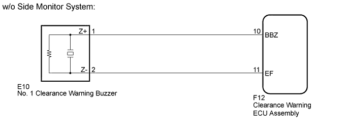
CHECK HARNESS AND CONNECTOR (CLEARANCE WARNING ECU ASSEMBLY - NO. 1 CLEARANCE WARNING BUZZER)
-
Disconnect the F12 clearance warning ECU connector.
-
Disconnect the E10 No. 1 clearance warning buzzer connector.
-
Measure the resistance according to the value(s) in the table below.
Standard Resistance Tester Connection Condition Specified Condition F12-10 (BBZ) - E10-1 (Z+) Always Below 1 Ω F12-11 (EF) - E10-2 (Z-) Always Below 1 Ω F12-10 (BBZ) - Body ground Always 10 kΩ or higher F12-11 (EF) - Body ground Always 10 kΩ or higher
- OKClick here
- NGClick here
-
- Click here
PROCEED TO NEXT CIRCUIT INSPECTION SHOWN IN PROBLEM SYMPTOMS TABLEClick here
- Click here
REPLACE NO. 1 CLEARANCE WARNING BUZZERClick here
- Click here
REPAIR OR REPLACE HARNESS OR CONNECTOR