TOYOTA PARKING ASSIST-SENSOR SYSTEM TERMINALS OF ECU

-
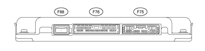
CHECK PARK ASSIST ECU (w/ Side Monitor System)
-
Disconnect the F75 and F76 parking assist ECU connectors.
-
Measure the voltage and resistance according to value(s) in the table below.
Terminal No. (Symbol) Wiring Color Terminal Description Condition Specified Condition F75-1 (+B) - F75-4 (GND1) L - W-B Power source signal Always 11 to 14 V F75-4 (GND1) - Body ground W-B - Body ground Ground Always Below 1 Ω F76-25 (CSSW) - F75-4 (GND1) Y - W-B back sonar or clearance sonar switch assembly power source signal Engine switch on (IG), back sonar or clearance sonar switch assembly on 11 to 14 V Engine switch on (IG), back sonar or clearance sonar switch assembly off Below 1 V F75-8 (IG) - F75-4 (GND1) G - W-B IG power source signal Engine switch on (IG) 11 to 14 V Engine switch off Below 1 V F75-9 (ACC) - F75-4 (GND1) GR - W-B ACC power source signal Engine switch on (ACC) 11 to 14 V Engine switch off Below 1 V -
Reconnect the F75 and F76 parking assist ECU connectors.
-
Measure the voltage and waveform according to value(s) in the table below.
Terminal No. (Symbol) Wiring Color Terminal Description Condition Specified Condition F76-3 (LIN2) - F76-4 (CSG2) LG - GR Rear sensor circuit power source Engine switch on (IG), back sonar or clearance sonar switch assembly on Waveform 1 F76-5 (CSB1) - F76-6 (CSG1) GR - R Front sensor circuit power source Engine switch off Below 1 V Engine switch on (IG), back sonar or clearance sonar switch assembly on 7.2 to 8.8 V F75-6 (EF) - F75-7 (BBZ) L - G No. 1 clearance warning buzzer signal Buzzer does not sound Below 1 V Buzzer sounding Waveform 2 F76-20 (CSB2) - F76-4 (CSG2) R - GR Rear sensor circuit power source Engine switch on (IG), back sonar or clearance sonar switch assembly on 7.2 to 8.8 V Engine switch off Below 1 V F76-23 (LIN1) - F76-6 (CSG1) LG - R Front sensor circuit power source Engine switch on (IG), back sonar or clearance sonar switch assembly on Waveform 1 -
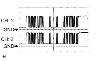
Using an oscilloscope, check waveform 1.
Waveform 1 (Reference) Item Content Terminal No. (Symbol)
-
F76-3 (LIN2) - F76-4 (CSG2)
-
F76-23 (LIN1) - F76-6 (CSG1)
Tool Setting 2 V/DIV., 1 msec./DIV. Condition Engine switch on (IG), back sonar or clearance sonar switch assembly on -
-
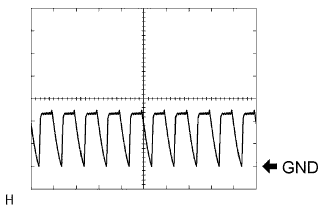
Using an oscilloscope, check waveform 2.
Waveform 2 (Reference) Item Content Terminal No. (Symbol) F75-6 (EF) - F75-7 (BBZ) Tool Setting 5 V/DIV., 1 msec./DIV. Condition Engine switch on (IG), shift lever moved to R Note
The waveform amplitude varies depending on the volume setting.
-
-
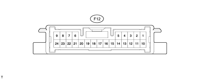
CHECK CLEARANCE WARNING ECU ASSEMBLY (w/o Side Monitor System)
-
Disconnect the F12 clearance warning ECU assembly connector.
-
Measure the voltage and resistance according to value(s) in the table below.
Terminal No. (Symbol) Wiring Color Terminal Description Condition Specified Condition F12-12 (CSSW) - F12-17 (GND1) Y - W-B back sonar or clearance sonar switch assembly power source signal Engine switch on (IG), back sonar or clearance sonar switch assembly on 11 to 14 V Engine switch on (IG), back sonar or clearance sonar switch assembly off Below 1 V F12-15 (IG) - F12-17 (GND1) G - W-B IG power source signal Engine switch on (IG) 11 to 14 V Engine switch off Below 1 V F12-17 (GND1) - Body ground W-B - Body ground Ground Always Below 1 Ω -
Reconnect the F12 clearance warning ECU assembly connector.
-
Measure the voltage and waveform according to value(s) in the table below.
Terminal No. (Symbol) Wiring Color Terminal Description Condition Specified Condition F12-7 (CSB2) - F12-18 (CSG2) R - GR Rear sensor circuit power source Engine switch on (IG), back sonar or clearance sonar switch assembly on 7.2 to 8.8 V Engine switch off Below 1 V F12-9 (LIN1) - F12-19 (CSG1) LG - R Front sensor circuit power source Engine switch on (IG), back sonar or clearance sonar switch assembly on Waveform 1 F12-10 (BBZ) - F12-11 (EF) G - L No. 1 clearance warning buzzer signal Buzzer not sounding Below 1 V Buzzer sounding Waveform 2 F12-21 (CSB1) - F12-9 (LIN1) GR - LG Front sensor circuit power source Engine switch on (IG), back sonar or clearance sonar switch assembly on 7.2 to 8.8 V Engine switch off Below 1 V F12-24 (LIN2) - F12-18 (CSG2) LG - GR Rear sensor circuit power source Engine switch on (IG), back sonar or clearance sonar switch assembly on Waveform 1 -
Using an oscilloscope, check waveform 1.
Waveform 1 (Reference) Item Content Terminal No. (Symbol)
-
F12-9 (LIN1) - F12-19 (CSG1)
-
F12-24 (LIN2) - F12-18 (CSG2)
Tool Setting 2 V/DIV., 1 msec./DIV. Condition Engine switch on (IG), back sonar or clearance sonar switch assembly on -
-
Using an oscilloscope, check waveform 2.
Waveform 2 (Reference) Item Content Terminal No. (Symbol) F12-10 (BBZ) - F12-11 (EF) Tool Setting 5 V/DIV., 1 msec./DIV. Condition Engine switch on (IG), shift lever moved to R Note
The waveform amplitude varies depending on the volume setting.
-