DESCRIPTION
These DTCs are stored when a malfunction occurs in the navigation antenna assembly (w/o Roof Antenna) or telephone antenna assembly (w/ Roof Antenna).
| DTC Code | DTC Detection Condition | Trouble Area |
|---|---|---|
| B15C0 | Navigation antenna error |
|
| B15C1 | Error of the power source to the navigation antenna |
INSPECTION PROCEDURE
PROCEDURE
- Click here
CHECK VEHICLE TYPE
-
Select the vehicle setting.
Table 1. Result Result Proceed to w/o Roof Antenna A w/ Roof Antenna, w/o DAB Function B w/ Roof Antenna, w/ DAB Function C
-
- Click here
CHECK CONNECTION OF NAVIGATION ANTENNA ASSEMBLY
-
Check if the navigation antenna assembly is securely connected to the multi-media module receiver assembly.
OK Navigation antenna assembly is securely connected.
- OKClick here
- NGClick here
-
- Click here
REPLACE NAVIGATION ANTENNA ASSEMBLY
-
Replace the navigation antenna assembly with a normally functioning one (Click here).
- NEXTClick here
-
- Click here
CLEAR DTC
-
Clear the DTCs (Click here).
- NEXTClick here
-
- Click here
CHECK DTC
-
Recheck for DTCs and check if the same DTCs are output again (Click here).
OK No DTCs are output.
- OKClick here
- NGClick here
-
- Click here
CHECK NO. 3 ANTENNA CORD SUB-ASSEMBLY
-
Disconnect the No. 3 antenna cord sub-assembly from telephone antenna assembly connector.
-
Disconnect the No. 3 antenna cord sub-assembly from No. 2 antenna cord sub-assembly.
-
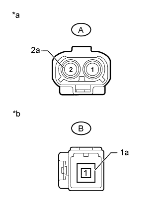
Measure the resistance according to the value(s) in the table below.
Standard Resistance Tester Connection Condition Specified Condition A-2 - B-1 Always Below 1 Ω A-2a - B-1a Always Below 1 Ω A-2 - Body ground Always 10 kΩ or higher A-2a - Body ground Always 10 kΩ or higher Table 2. Text in Illustration *a Front view of wire harness connector
(to Telephone Antenna Assembly)
*b Front view of wire harness connector
(to No. 2 Antenna Cord Sub-assembly)
- OKClick here
- NGClick here
-
- Click here
CHECK NO. 2 ANTENNA CORD SUB-ASSEMBLY
-
Disconnect the No. 2 antenna cord sub-assembly from No. 3 antenna cord sub-assembly.
-
Disconnect the No. 2 antenna cord sub-assembly from antenna cord sub-assembly.
-
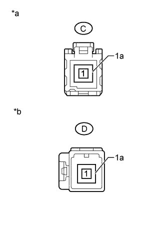
Measure the resistance according to the value(s) in the table below.
Standard Resistance Tester Connection Condition Specified Condition C-1 - D-1 Always Below 1 Ω C-1a - D-1a Always Below 1 Ω C-1 - Body ground Always 10 kΩ or higher C-1a - Body ground Always 10 kΩ or higher Table 3. Text in Illustration *a Front view of wire harness connector
(to No. 3 Antenna Cord Sub-assembly)
*b Front view of wire harness connector
(to Antenna Cord Sub-assembly)
- OKClick here
- NGClick here
-
- Click here
CHECK ANTENNA CORD SUB-ASSEMBLY
-
Disconnect the antenna cord sub-assembly from No. 2 antenna cord sub-assembly.
-
Disconnect the antenna cord sub-assembly from multi-media module receiver assembly.
-
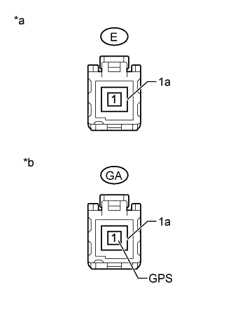
Measure the resistance according to the value(s) in the table below.
Standard Resistance Tester Connection Condition Specified Condition E-1 - GA-1 (GPS) Always Below 1 Ω E-1a - GA-1a Always Below 1 Ω E-1 - Body ground Always 10 kΩ or higher E-1a - Body ground Always 10 kΩ or higher Table 4. Text in Illustration *a Front view of wire harness connector
(to No. 2 Antenna Cord Sub-assembly)
*b Front view of wire harness connector
(to Multi-media Module Receiver Assembly)
- OKClick here
- NGClick here
-
- Click here
REPLACE TELEPHONE ANTENNA ASSEMBLY
-
Replace the telephone antenna assembly with a normally functioning one (Click here).
- NEXTClick here
-
- Click here
CLEAR DTC
-
Clear the DTCs (Click here).
- NEXTClick here
-
- Click here
CHECK DTC
-
Recheck for DTCs and check if the same DTCs are output again (Click here).
OK No DTCs are output.
- OKClick here
- NGClick here
-
- Click here
SECURELY CONNECT NAVIGATION ANTENNA ASSEMBLY
- Click here
REPLACE MULTI-MEDIA MODULE RECEIVER ASSEMBLYClick here
- Click here
END (NAVIGATION ANTENNA ASSEMBLY IS DEFECTIVE)
- Click here
REPLACE DIGITAL AUDIO BROADCASTING ANTENNA ASSEMBLYClick here
- Click here
REPLACE NO. 3 ANTENNA CORD SUB-ASSEMBLYClick here
- Click here
REPLACE NO. 2 ANTENNA CORD SUB-ASSEMBLYClick here
- Click here
REPLACE ANTENNA CORD SUB-ASSEMBLYClick here
- Click here
REPLACE MULTI-MEDIA MODULE RECEIVER ASSEMBLYClick here
- Click here
END (TELEPHONE ANTENNA ASSEMBLY IS DEFECTIVE)
- Click here
CHECK DIGITAL AUDIO BROADCASTING ANTENNA ASSEMBLY
-
Disconnect the digital audio broadcasting antenna assembly from telephone antenna assembly connector.
-
Disconnect the digital audio broadcasting antenna assembly from No. 2 antenna cord sub-assembly.
-
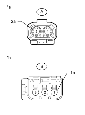
Measure the resistance according to the value(s) in the table below.
Standard Resistance Tester Connection Condition Specified Condition A-2 - B-1 Always Below 1 Ω A-2a - B-1a Always Below 1 Ω A-2 - Body ground Always 10 kΩ or higher A-2a - Body ground Always 10 kΩ or higher Table 5. Text in Illustration *a Front view of wire harness connector
(to Telephone Antenna Assembly)
*b Front view of wire harness connector
(to No. 2 Antenna Cord Sub-assembly)
- OKClick here
- NGClick here
-
- Click here
CHECK NO. 2 ANTENNA CORD SUB-ASSEMBLY
-
Disconnect the No. 2 antenna cord sub-assembly from digital audio broadcasting antenna assembly.
-
Disconnect the No. 2 antenna cord sub-assembly from antenna cord sub-assembly.
-
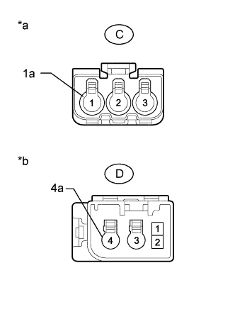
Measure the resistance according to the value(s) in the table below.
Standard Resistance Tester Connection Condition Specified Condition C-1 - D-4 Always Below 1 Ω C-1a - D-4a Always Below 1 Ω C-1 - Body ground Always 10 kΩ or higher C-1a - Body ground Always 10 kΩ or higher Table 6. Text in Illustration *a Front view of wire harness connector
(to Digital Audio Broadcasting Antenna Assembly)
*b Front view of wire harness connector
(to Antenna Cord Sub-assembly)
- OKClick here
- NGClick here
-
- Click here
CHECK ANTENNA CORD SUB-ASSEMBLY
-
Disconnect the antenna cord sub-assembly from No. 2 antenna cord sub-assembly.
-
Disconnect the antenna cord sub-assembly from multi-media module receiver assembly.
-
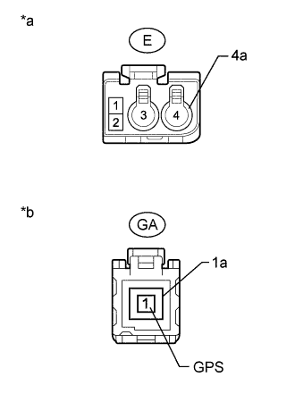
Measure the resistance according to the value(s) in the table below.
Standard Resistance Tester Connection Condition Specified Condition E-4 - GA-1 (GPS) Always Below 1 Ω E-4a - GA-1a Always Below 1 Ω E-4 - Body ground Always 10 kΩ or higher E-4a - Body ground Always 10 kΩ or higher Table 7. Text in Illustration *a Front view of wire harness connector
(to No. 2 Antenna Cord Sub-assembly)
*b Front view of wire harness connector
(to Multi-media Module Receiver Assembly)
- OKClick here
- NGClick here
-
- Click here
REPLACE TELEPHONE ANTENNA ASSEMBLY
-
Replace the telephone antenna assembly with a normally functioning one (Click here).
- NEXTClick here
-
- Click here
CLEAR DTC
-
Clear the DTCs (Click here).
- NEXTClick here
-
- Click here
CHECK DTC
-
Recheck for DTCs and check if the same DTCs are output again (Click here).
OK No DTCs are output.
- OKClick here
- NGClick here
-