- Click here
INSTALL HAZARD WARNING SIGNAL SWITCH ASSEMBLY
-
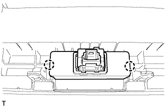
Attach the 2 claws to install the hazard warning switch.
-
- Click here
INSTALL CLOCK ASSEMBLY
-
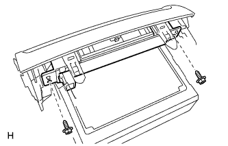
Install the clock with the 2 screws.
-
- Click here
INSTALL NO. 1 RADIO BRACKET
-
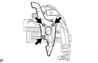
Install the bracket with the 3 bolts.
3.0 N*m 30 kgf*cm 26 in.*lbf
-
- Click here
INSTALL NO. 2 RADIO BRACKET
-
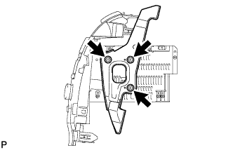
Install the bracket with the 3 bolts.
3.0 N*m 30 kgf*cm 26 in.*lbf
-
- Click here
INSTALL RADIO RECEIVER ASSEMBLY WITH BRACKET
-
Connect the connectors.
-
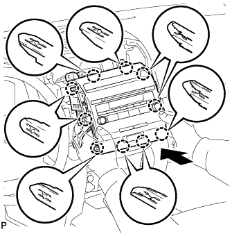
Insert the radio receiver to attach the 10 claws on its backside.
Note:When inserting the radio receiver, do not press the knobs on it.
-
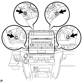
Install the radio receiver with the 2 screws and 2 bolts.
Bolt 12 N*m 122 kgf*cm 9 ft.*lbf
-
-
Click here
INSTALL NO. 4 INSTRUMENT PANEL REGISTER ASSEMBLY
-
Connect the connector.
-
Attach the 6 claws to install the No. 4 instrument panel register.
-
-
Click here
INSTALL NO. 3 INSTRUMENT PANEL REGISTER ASSEMBLY
-
Connect the connector.
-
Attach the 6 claws to install the No. 3 instrument panel register.
-
-
Click here
INSTALL NO. 1 SPEAKER OPENING COVER ASSEMBLY
-
Attach the 8 claws to install the opening cover.
-
- Click here
CONNECT CABLE TO NEGATIVE BATTERY TERMINAL
Note:When disconnecting the cable, some systems need to be initialized after the cable is reconnected (Click here).