AUDIO AND VISUAL SYSTEM (w/o Stereo Component Amplifier) Illumination Circuit
DESCRIPTION
Power is supplied to the radio receiver and steering pad switch illumination when the light control switch is in the tail or head position.
WIRING DIAGRAM
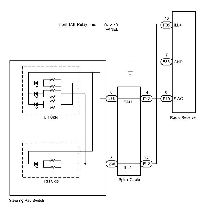
INSPECTION PROCEDURE
CAUTION:
The vehicle is equipped with an SRS (Supplemental Restraint System) which includes components such as airbags. Before servicing (including removal or installation of parts), be sure to read the Precaution for the SRS Click here.
Note
Inspect the fuses for circuits related to this system before performing the following inspection procedure.
PROCEDURE
-
CHECK ILLUMINATION
-
Check if the illumination for the steering pad switch, glove box light, cigarette lighter, or others (seat heater switch, front seat memory switch, etc.) comes on when the light control switch is turned to the head or tail position.
Result Result Proceed to Illumination comes on for all components except steering pad switch. A Illumination comes on for all components except radio receiver. B No illumination comes on for radio receiver, glove box light, front seat memory switch, cigarette lighter, etc. C
B 
CHECK HARNESS AND CONNECTOR (RADIO RECEIVER - TAIL RELAY AND BODY GROUND) Click here
C 
GO TO LIGHTING SYSTEM Click here
A 
-
-
CHECK HARNESS AND CONNECTOR (SPIRAL CABLE - TAIL RELAY)
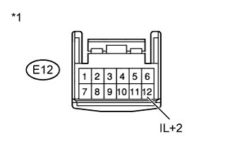
Text in Illustration *1 Front view of wire harness connector
(to Spiral Cable)
-
Disconnect the E12 cable connector.
-
Measure the voltage according to the value(s) in the table below.
Standard Voltage Tester Connection Switch Condition Specified Condition E12-12 (IL+2) - Body ground Light control switch tail or head 11 to 14 V
NG
REPAIR OR REPLACE HARNESS OR CONNECTOR
OK
-
-
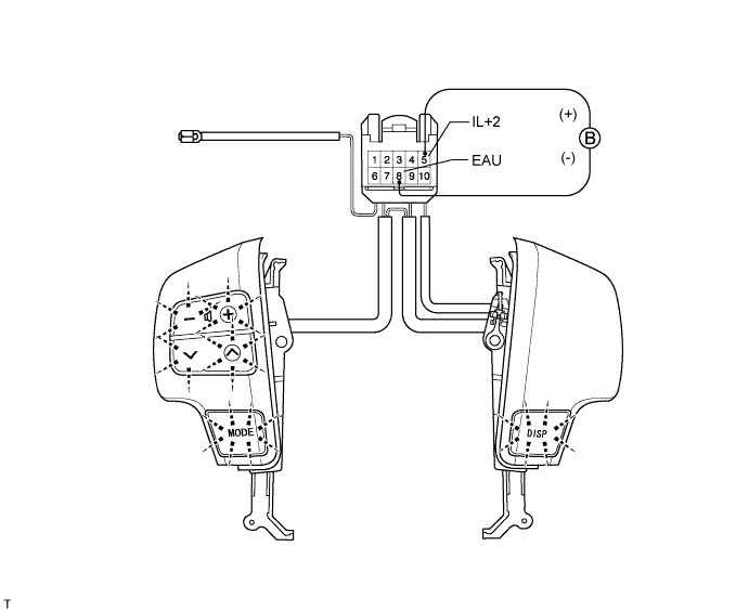
INSPECT STEERING PAD SWITCH ASSEMBLY
-
Disconnect the z36 switch connector.
-
Apply battery voltage to the terminals of the connector, and check the LED illumination condition.
OK Measurement Condition Specified Condition Battery positive (+) → Terminal 5 (IL+2)
Battery negative (-) → Terminal 8 (EAU)
Light illuminates
NG
REPLACE STEERING PAD SWITCH ASSEMBLY Click here
OK
-
-
INSPECT SPIRAL CABLE SUB-ASSEMBLY
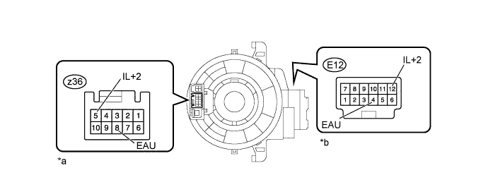
Text in Illustration *a Steering Pad Switch Side *b Vehicle Side
-
Disconnect the E12 and z36 cable connectors.
-
Measure the resistance according to the value(s) in the table below.
Standard Resistance Tester Connection Condition Specified Condition E12-12 (IL+2) - z36-5 (IL+2) Spiral cable is turned 2.5 rotations counterclockwise Below 3 Ω Spiral cable is centered Spiral cable is turned 2.5 rotations clockwise E12-4 (EAU) - z36-8 (EAU) Spiral cable is turned 2.5 rotations counterclockwise Below 3 Ω Spiral cable is centered Spiral cable is turned 2.5 rotations clockwise CAUTION:
The spiral cable is an important part of the SRS airbag system. Incorrect removal or installation of the spiral cable may prevent the airbag from deploying. Be sure to read the Precaution for the SRS Click here.
NG
REPLACE SPIRAL CABLE SUB-ASSEMBLY Click here
OK
-
-
CHECK HARNESS AND CONNECTOR (SPIRAL CABLE - RADIO RECEIVER)
-
Disconnect the F19 receiver connector.
-
Disconnect the E12 cable connector.
-
Measure the resistance according to the value(s) in the table below.
Standard Resistance Tester Connection Condition Specified Condition F19-6 (SWG) - E12-4 (EAU) Always Below 1 Ω F19-6 (SWG) - Body ground Always 10 kΩ or higher
NG
REPAIR OR REPLACE HARNESS OR CONNECTOR
OK 
PROCEED TO NEXT SUSPECTED AREA SHOWN IN PROBLEM SYMPTOMS TABLE Click here
-
-
CHECK HARNESS AND CONNECTOR (RADIO RECEIVER - TAIL RELAY AND BODY GROUND)
-
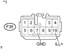
Text in Illustration *1 Front view of wire harness connector
(to Radio Receiver)
Disconnect the F35 receiver connector.
-
Measure the resistance according to the value(s) in the table below.
Standard Resistance Tester Connection Condition Specified Condition F35-7 (GND) - Body ground Always Below 1 Ω -
Measure the voltage according to the value(s) in the table below.
Standard Voltage Tester Connection Switch Condition Specified Condition F35-10 (ILL+) - Body ground Light control switch
tail or head
11 to 14 V
NG
REPAIR OR REPLACE HARNESS OR CONNECTOR
OK
REPLACE RADIO RECEIVER ASSEMBLY Click here
-