AUDIO AND VISUAL SYSTEM (w/o Navigation System) Speaker Circuit
DESCRIPTION
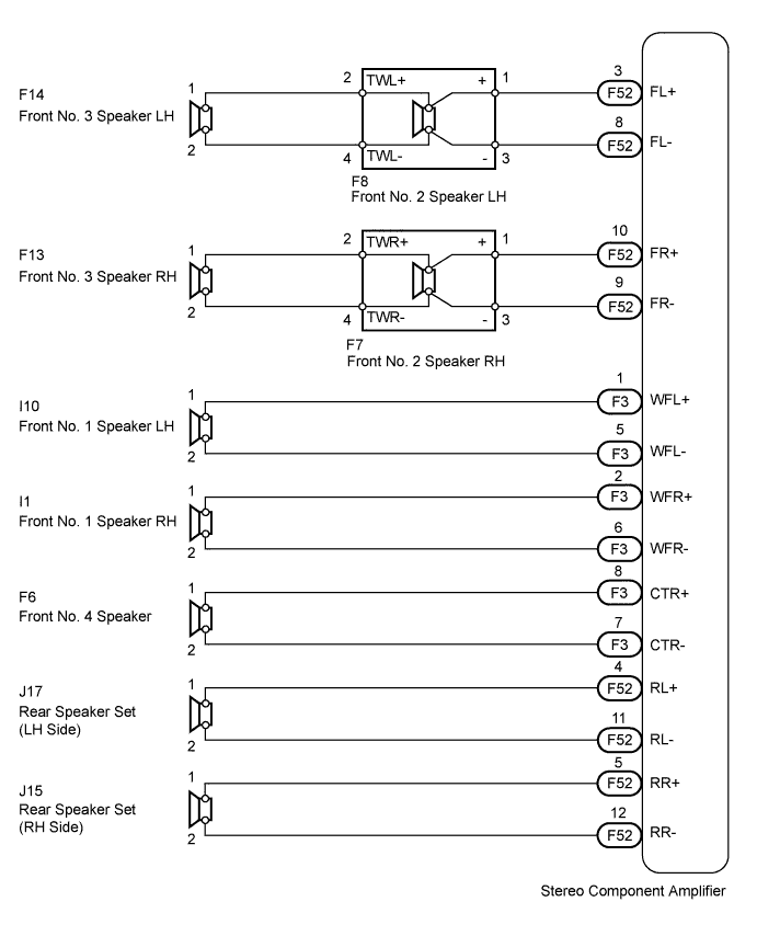
The stereo component amplifier sends sound signals to the speakers.
WIRING DIAGRAM
INSPECTION PROCEDURE
PROCEDURE
-
CHECK SPEAKER
-
Check the malfunctioning speakers.
Result Result Proceed to Front No. 4 speaker A Front No. 2 speaker B Front No. 1 speaker C Front No. 3 speaker D Rear speaker set E
B 
INSPECT FRONT NO. 2 SPEAKER ASSEMBLY Click here
C
INSPECT FRONT NO. 1 SPEAKER ASSEMBLY Click here
D
INSPECT FRONT NO. 3 SPEAKER ASSEMBLY Click here
E
INSPECT REAR SPEAKER SET Click here
A 
-
-
INSPECT FRONT NO. 4 SPEAKER ASSEMBLY
-
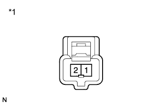
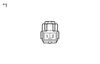
Text in Illustration *1 Component without harness connected
(Front No. 4 Speaker)
Disconnect the F6 speaker connector.
-
Measure the resistance according to the value(s) in the table below.
Standard Resistance Tester Connection Condition Specified Condition 1 - 2 Always 6 Ω
NG 
REPLACE FRONT NO. 4 SPEAKER ASSEMBLY Click here
OK
-
-
CHECK HARNESS AND CONNECTOR (STEREO COMPONENT AMPLIFIER - FRONT NO. 4 SPEAKER)
-
Disconnect the F6 speaker connector.
-
Disconnect the F3 amplifier connector.
-
Measure the resistance according to the value(s) in the table below.
Standard Resistance Tester Connection Condition Specified Condition F3-8 (CTR+) - F6-1 Always Below 1 Ω F3-7 (CTR-) - F6-2 Always Below 1 Ω F3-8 (CTR+) - Body ground Always 10 kΩ or higher F3-7 (CTR-) - Body ground Always 10 kΩ or higher
NG
REPAIR OR REPLACE HARNESS OR CONNECTOR
OK 
REPLACE STEREO COMPONENT AMPLIFIER ASSEMBLY Click here
-
-
INSPECT FRONT NO. 2 SPEAKER ASSEMBLY
-
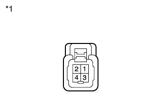
Text in Illustration *1 Component without harness connected
(Front No. 2 Speaker)
Disconnect the F8 and F7 speaker connectors.
-
Measure the resistance according to the value(s) in the table below.
Standard Resistance Tester Connection Condition Specified Condition 1 - 2 Always Below 1 Ω 3 - 4 Always Below 1 Ω 2 - 4 Always 4 Ω
NG
REPLACE FRONT NO. 2 SPEAKER ASSEMBLY Click here
OK
-
-
CHECK HARNESS AND CONNECTOR (STEREO COMPONENT AMPLIFIER - FRONT NO. 2 SPEAKER)
-
Disconnect the F52 amplifier connector.
-
Disconnect the F8 and F7 speaker connectors.
-
Measure the resistance according to the value(s) in the table below.
Standard Resistance for LH Tester Connection Condition Specified Condition F52-3 (FL+) - F8-1 (+) Always Below 1 Ω F52-8 (FL-) - F8-3 (-) Always Below 1 Ω F52-3 (FL+) - Body ground Always 10 kΩ or higher F52-8 (FL-) - Body ground Always 10 kΩ or higher for RH Tester Connection Condition Specified Condition F52-10 (FR+) - F7-1 (+) Always Below 1 Ω F52-9 (FR-) - F7-3 (-) Always Below 1 Ω F52-10 (FR+) - Body ground Always 10 kΩ or higher F52-9 (FR-) - Body ground Always 10 kΩ or higher
NG
REPAIR OR REPLACE HARNESS OR CONNECTOR
OK
REPLACE STEREO COMPONENT AMPLIFIER ASSEMBLY Click here
-
-
INSPECT FRONT NO. 1 SPEAKER ASSEMBLY
-
Text in Illustration *1 Component without harness connected
(Front No. 1 Speaker)
Disconnect the I10 and I1 speaker connectors.
-
Measure the resistance according to the value(s) in the table below.
Standard Resistance Tester Connection Condition Specified Condition 1 - 2 Always 3 Ω
NG
REPLACE FRONT NO. 1 SPEAKER ASSEMBLY Click here
OK
-
-
CHECK HARNESS AND CONNECTOR (STEREO COMPONENT AMPLIFIER - FRONT NO. 1 SPEAKER)
-
Disconnect the I10 and I1 speaker connectors.
-
Disconnect the F3 amplifier connector.
-
Measure the resistance according to the value(s) in the table below.
Standard Resistance for LH Tester Connection Condition Specified Condition F3-1 (WFL+) - I10-1 Always Below 1 Ω F3-5 (WFL-) - I10-2 Always Below 1 Ω F3-1 (WFL+) - Body ground Always 10 kΩ or higher F3-5 (WFL-) - Body ground Always 10 kΩ or higher for RH Tester Connection Condition Specified Condition F3-2 (WFR+) - I1-1 Always Below 1 Ω F3-6 (WFR-) - I1-2 Always Below 1 Ω F3-2 (WFR+) - Body ground Always 10 kΩ or higher F3-6 (WFR-) - Body ground Always 10 kΩ or higher
NG
REPAIR OR REPLACE HARNESS OR CONNECTOR
OK
REPLACE STEREO COMPONENT AMPLIFIER ASSEMBLY Click here
-
-
INSPECT FRONT NO. 3 SPEAKER ASSEMBLY
-
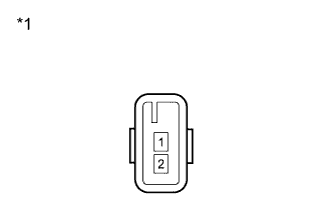
Text in Illustration *1 Component without harness connected
(Front No. 3 Speaker)
Disconnect the F14 and F13 speaker connectors.
-
Measure the resistance according to the value(s) in the table below.
Standard Resistance Tester Connection Condition Specified Condition 1 - 2 Always 4 Ω
NG
REPLACE FRONT NO. 3 SPEAKER ASSEMBLY Click here
OK
-
-
INSPECT FRONT NO. 2 SPEAKER ASSEMBLY
-
Text in Illustration *1 Component without harness connected
(Front No. 2 Speaker)
Disconnect the F8 and F7 speaker connectors.
-
Measure the resistance according to the value(s) in the table below.
Standard Resistance Tester Connection Condition Specified Condition 1 - 2 Always Below 1 Ω 3 - 4 Always Below 1 Ω 2 - 4 Always 4 Ω
NG
REPLACE FRONT NO. 2 SPEAKER ASSEMBLY Click here
OK
REPAIR OR REPLACE HARNESS OR CONNECTOR (FRONT NO. 2 SPEAKER - FRONT NO. 3 SPEAKER)
-
-
INSPECT REAR SPEAKER SET
-
Text in Illustration *1 Component without harness connected
(Rear Speaker Set)
Disconnect the J17 and J15 speaker connectors.
-
Measure the resistance according to the value(s) in the table below.
Standard Resistance Tester Connection Condition Specified Condition 1 - 2 Always 4 Ω
NG
REPLACE REAR SPEAKER SET Click here
OK
-
-
CHECK HARNESS AND CONNECTOR (STEREO COMPONENT AMPLIFIER - REAR SPEAKER SET)
-
Disconnect the F52 amplifier connector.
-
Disconnect the J17 and J15 speaker connectors.
-
Measure the resistance according to the value(s) in the table below.
Standard Resistance for LH Tester Connection Condition Specified Condition F52-4 (RL+) - J17-1 Always Below 1 Ω F52-11 (RL-) - J17-2 Always Below 1 Ω F52-4 (RL+) - Body ground Always 10 kΩ or higher F52-11 (RL-) - Body ground Always 10 kΩ or higher for RH Tester Connection Condition Specified Condition F52-5 (RR+) - J15-1 Always Below 1 Ω F52-12 (RR-) - J15-2 Always Below 1 Ω F52-5 (RR+) - Body ground Always 10 kΩ or higher F52-12 (RR-) - Body ground Always 10 kΩ or higher
NG
REPAIR OR REPLACE HARNESS OR CONNECTOR
OK
REPLACE STEREO COMPONENT AMPLIFIER ASSEMBLY Click here
-