AUDIO AND VISUAL SYSTEM (w/ Navigation System) TERMINALS OF ECU

-
MULTI-MEDIA MODULE RECEIVER ASSEMBLY
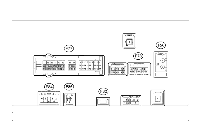
Terminal No. (Symbol) Wiring Color Terminal Description Condition Specified Condition F77-1 (CANH) P CAN communication signal - - F77-2 (CANL) B CAN communication signal - - F77-7 (TX1+) W AVC-LAN communication signal - - F77-8 (TX1-) L AVC-LAN communication signal - - F77-10 (VMTF) - F77-12 (GND1) V - W-B Visual mute signal When image on display switches 3.5 V or higher → Below 1 V → 3.5 V or higher F77-12 (GND1) - Body ground W-B - Body ground Ground Always Below 1 Ω F77-13 (ILL-) - F77-12 (GND1) W - W-B Illumination signal Engine switch on (IG), light control switch off → tail or head (Light intensity is not max. or min.) Below 1 V → Pulse generation F77-14 (ILL+) - F77-12 (GND1) G - W-B Illumination signal Engine switch on (IG), light control switch off → tail or head position Below 1 V → 11 to 14 V F77-15 (IG) - F77-12 (GND1) G - W-B Power source (IG) Engine switch on (IG) 11 to 14 V Engine switch off Below 1 V F77-16 (ACC1) - F77-12 (GND1) GR - W-B Power source (ACC) Engine switch on (ACC) 11 to 14 V Engine switch off Below 1 V F77-17 (+B1) - F77-12 (GND1) R - W-B Power source Always 11 to 14 V F77-27 (MIN+) - F77-12 (GND1) B - W-B Microphone voice signal See "Microphone & Voice Recognition Check" in Operation Check Click here
- F77-28 (SGND) - F77-12 (GND1) Shielded - W-B Shield ground Always Below 1 V F77-29 (MACC) - F77-12 (GND1) W - W-B Telephone microphone assembly power supply Engine switch off Below 1 V Engine switch on (ACC) 4 to 6 V F77-30 (SW1) - F77-32 (SWG) L - W Steering pad switch signal Steering pad switch not operated 4.44 to 5.43 V Seek+ switch pushed 0.45 to 0.65 V Seek- switch pushed 1.19 to 1.49 V Vol+ switch pushed 2.09 to 2.54 V Vol- switch pushed 3.2 to 3.88 V F77-31 (SW2) - F77-32 (SWG) P - W Steering pad switch signal Steering pad switch not operated 4.44 to 5.43 V MODE switch pushed 0.45 to 0.65 V On hook switch pushed 1.19 to 1.49 V Off hook switch pushed 2.09 to 2.54 V Voice switch pushed 3.2 to 3.88 V F77-32 (SWG) - Body ground W - Body ground Steering pad switch signal Always Below 1 V F77-35 (UIND) R UART communication signal - - F77-36 (UPSW) P UART communication signal - - F77-45 (TX3+) B AVC-LAN communication signal - - F77-46 (TX3-) W AVC-LAN communication signal - - F77-48 (MIN-) - F77-12 (GND1) R - W-B Microphone voice signal See "Microphone & Voice Recognition Check" in Operation Check Click here
- F77-49 (SNS2) - F77-12 (GND1) GR - W-B Microphone connection detection signal Always Below 1 V F77-56 (SPD) - F77-12 (GND1) V - W-B Speed signal from combination meter assembly See "Vehicle Signal Check Mode" in Operation Check Click here
- F78-5 (AGND) - Body ground Shielded - Body ground Shield ground Always Below 1 V F78-6 (VV+) - F77-12 (GND1) B - W-B Display signal DVD is playing A waveform synchronized with display signal is output. (Refer to waveform) F78-7 (VAR+) - F78-15 (VA-) W - R Sound signal (Right) AUX audio device playing (When stereo jack adapter used) A waveform synchronized with sound is output. F78-8 (VAL+) - F78-15 (VA-) B - R Sound signal (Left) AUX audio device playing (When stereo jack adapter used) A waveform synchronized with sound is output. F78-13 (SG) - Body ground Shielded - Body ground Shield ground Always Below 1 V F78-14 (VV-) - F77-12 (GND1) W - W-B Ground Always Below 1 V F78-15 (VA-) - F77-12 (GND1) R - W-B Sound signal ground Always Below 1 V F78-16 (ADPG) - F77-12 (GND1) R - W-B External device connector detection signal External device connected Below 1 V External device not connected 2.1 to 3 V F84-1 (WUO) - F77-12 (GND1) W - W-B MOST communication signal Engine switch on (ACC) 4.5 V or higher Engine switch off Below 1 V F84-2 (MI+) B MOST communication signal - - F84-3 (MI-) B MOST communication signal - - F84-4 (SLDI) - Body ground Shielded - Body ground Shield ground Always Below 1 V F84-5 (MO+) B MOST communication signal - - F84-6 (MO-) B MOST communication signal - - F84-7 (SLDO) - Body ground Shielded - Body ground Shield ground Always Below 1 V F86-1 (USV1) # Power source - - F86-2 (US1-) # Data signal - - F86-3 (US1+) # Data signal - - F86-4 (UGD1) # Ground - - F86-5 (USG1) - Shield ground - -
-
#: There is no wire color information.
-
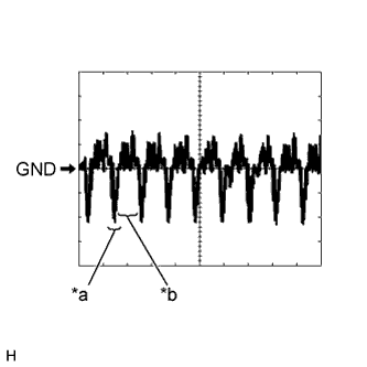
Text in Illustration *a Synchronization Signal *b Video Waveform Reference (Oscilloscope waveform):
-
Waveform
Item Content Measurement Terminal F78-6 (VV+) - F77-12 (GND1) Measurement Setting 200 mV/DIV., 10 μs/DIV. Condition DVD is playing Tech Tips
The video waveform changes according to the image input from the multi-media module receiver assembly, but the synchronization signal does not change.
-
-
-
STEREO COMPONENT AMPLIFIER ASSEMBLY
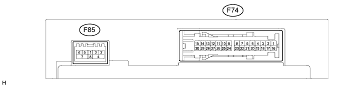
Terminal No. (Symbol) Wiring Color Terminal Description Condition Specification F74-1 (+B) - F74-3 (GND)*1 B - W-B Power source Always 11 to 14 V F74-3 (GND) - Body ground W-B - Body ground Ground Always Below 1 Ω F74-4 (WFL+) - F74-3 (GND) P - W-B Sound signal (Front Left) Audio system playing A waveform synchronized with sound is output. F74-5 (WFR+) - F74-3 (GND) LG - W-B Sound signal (Front Right) Audio system playing A waveform synchronized with sound is output. F74-6 (WF1+) - F74-3 (GND)*1 W - W-B Sound signal (Woofer) Audio system playing A waveform synchronized with sound is output. F74-7 (CTR+) - F74-3 (GND) W - W-B Sound signal (Front Center) Audio system playing A waveform synchronized with sound is output. F74-8 (WF2+) - F74-3 (GND)*1 R - W-B Sound signal (Woofer) Audio system playing A waveform synchronized with sound is output. F74-10 (SL+) - F74-3 (GND)*1 W - W-B Sound signal (Rear Left) Audio system playing A waveform synchronized with sound is output. F74-11 (SR+) - F74-3 (GND)*1 W - W-B Sound signal (Rear Right) Audio system playing A waveform synchronized with sound is output. F74-12 (FL+) - F74-3 (GND) W - W-B Sound signal (Front Left) Audio system playing A waveform synchronized with sound is output. F74-13 (FR+) - F74-3 (GND) W - W-B Sound signal (Front Right) Audio system playing A waveform synchronized with sound is output. F74-14 (R-L+) - F74-3 (GND)*1 W - W-B Sound signal (Rear Left) Audio system playing A waveform synchronized with sound is output F74-14 (RL+) - F74-3 (GND)*2 B - W-B F74-15 (R-R+) - F74-3 (GND)*1 W - W-B Sound signal (Rear Right) Audio system playing A waveform synchronized with sound is output. F74-15 (RR+) - F74-3 (GND)*2 R - W-B F74-16 (+B2) - F74-3 (GND) L - W-B Power source Always 11 to 14 V F74-17 (SPD) - F74-3 (GND) V - W-B Vehicle speed signal Engine switch on (IG)
Wheel being rotated
Pulse generation F74-18 (GND2) - Body ground W-B - Body ground Ground Always Below 1 Ω F74-19 (WFL-) - F74-3 (GND) V - W-B Sound signal (Front Left) Audio system playing A waveform synchronized with sound is output. F74-20 (WFR-) - F74-3 (GND) L - W-B Sound signal (Front Right) Audio system playing A waveform synchronized with sound is output. F74-21 (WF1-) - F74-3 (GND)*1 B - W-B Sound signal (Woofer) Audio system playing A waveform synchronized with sound is output. F74-22 (CTR-) - F74-3 (GND) B - W-B Sound signal (Front Center) Audio system playing A waveform synchronized with sound is output. F74-23 (WF2-) - F74-3 (GND)*1 W - W-B Sound signal (Woofer) Audio system playing A waveform synchronized with sound is output. F74-25 (SL-) - F74-3 (GND)*1 B - W-B Sound signal (Rear Left) Audio system playing A waveform synchronized with sound is output. F74-26 (SR-) - F74-3 (GND)*1 B - W-B Sound signal (Rear Right) Audio system playing A waveform synchronized with sound is output. F74-27 (FL-) - F74-3 (GND) B - W-B Sound signal (Front Left) Audio system playing A waveform synchronized with sound is output. F74-28 (FR-) - F74-3 (GND) B - W-B Sound signal (Front Right) Audio system playing A waveform synchronized with sound is output. F74-29 (R-L-) - F74-3 (GND)*1 B - W-B Sound signal (Rear Left) Audio system playing A waveform synchronized with sound is output. F74-29 (RL-) - F74-3 (GND)*2 Y - W-B F74-30 (R-R-) - F74-3 (GND)*1 B - W-B Sound signal (Rear Right) Audio system playing A waveform synchronized with sound is output. F74-30 (RR-) - F74-3 (GND)*2 W - W-B F85-1 (WUO) - F74-3 (GND) W - W-B MOST communication wake-up signal Engine switch on (ACC) 4.5 V or higher F85-2 (MI+) B MOST communication signal - - F85-3 (MI-) B MOST communication signal - - F85-4 (SLDI) - Body ground Shielded - Body ground Shield ground Always Below 1 Ω F85-5 (MO+) B MOST communication signal - - F85-6 (MO-) B MOST communication signal - - F85-7 (SLDO) - Body ground Shielded - Body ground Shield ground Always Below 1 Ω F85-8 (WU1) - F74-3 (GND) W - W-B MOST communication wake-up signal Engine switch on (ACC) 4.5 V or higher
-
*1: for 14 Speakers
-
*2: for 9 Speakers
-
-
MULTI-DISPLAY ASSEMBLY
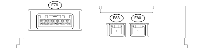
Terminal No. (Symbol) Wiring Color Terminal Description Condition Specified Condition F79-2 (ILL) - F79-13 (GND1) G - BR Illumination signal Engine switch on (IG), light control switch off Below 1 V Tail or head position 11 to 14 V F79-3 (UPSW) P UART communication signal - - F79-4 (UIND) R UART communication signal - - F79-7 (TX+) B AVC-LAN communication signal - - F79-11 (VMTI) - F79-13 (GND1) V - BR Visual mute signal When image on display switches 3.5 V or higher → Below 1 V → 3.5 V or higher F79-12 (+B2) - F79-13 (GND1) R - BR Power source Always 11 to 14 V F79-13 (GND1) - Body ground BR - Body ground Ground Always Below 1 Ω F79-14 (ILL-) - F79-13 (GND1) W - BR Ground Always Below 1 Ω F79-19 (TX-) W AVC-LAN communication signal - - F79-23 (IG) - F79-13 (GND1) G - BR Power source (IG) Engine switch on (IG) 11 to 14 V Engine switch off Below 1 V F79-24 (ACC) - F79-13 (GND1) GR - BR Power source (ACC) Engine switch on (ACC) 11 to 14 V Engine switch off Below 1 V -
TELEVISION DISPLAY ASSEMBLY Click here