- Click here
DISCONNECT CABLE FROM NEGATIVE BATTERY TERMINAL
CAUTION:Wait at least 90 seconds after disconnecting the cable from the negative (-) battery terminal to disable the SRS system.
Note:When disconnecting the cable, some systems need to be initialized after the cable is reconnected (Click here).
- Click here
REMOVE LOWER STEERING COLUMN COVER
-
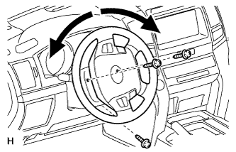
Remove the 3 screws.
Tip:Turn the steering wheel to the right and left as necessary to remove the 2 screws.
-
Detach the 2 claws to remove the lower steering column cover.
-
- Click here
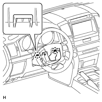
REMOVE UPPER STEERING COLUMN COVER
-
Detach the 4 clips.
-
Detach the claw to remove the upper steering column cover.
-
- Click here
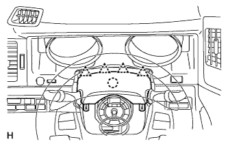
REMOVE DRIVER SIDE KNEE AIRBAG ASSEMBLY
-
Remove the driver side knee airbag assembly (Click here).
-
- Click here
INSPECT TILT MOTOR
-
Inspect the tilt motor.
-
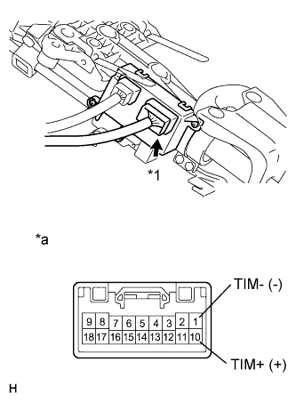
Disconnect connector A from the multiplex tilt and telescopic ECU.
-
Apply battery voltage to the tilt motor connector, and check the steering wheel tilt operation.
Table 1. Text in Illustration *1 Connector A *a Front view of wire harness connector
(to Multiplex Tilt and Telescopic ECU)
Table 2. OK Measurement Condition Specified Condition Battery positive (+) → Terminal 10 (TIM+)
Battery negative (-) → Terminal 1(TIM-)
Steering wheel tilts up -
Apply battery voltage to the tilt motor connector, and check the steering wheel tilt operation.
Table 3. Text in Illustration *1 Connector A *a Front view of wire harness connector
(to Multiplex Tilt and Telescopic ECU)
Table 4. OK Measurement Condition Specified Condition Battery positive (+) → Terminal 1 (TIM-)
Battery negative (-) → Terminal 10 (TIM+)
Steering wheel tilts down If the steering wheel does not tilt down, replace the steering column assembly.
-
-
- Click here
INSPECT TELESCOPIC MOTOR
-
Inspect the telescopic motor.
-
Disconnect connector B from the multiplex tilt and telescopic ECU.
-
Apply battery voltage to the telescopic motor connector, and check the steering column operation.
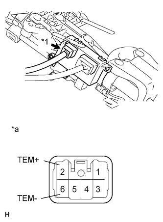
Table 5. Text in Illustration *1 Connector B *a Front view of wire harness connector
(to Multiplex Tilt and Telescopic ECU)
Table 6. OK Measurement Condition Specified Condition Battery positive (+) → Terminal 2 (TEM+)
Battery negative (-) → Terminal 6 (TEM-)
Steering column contracts -
Apply battery voltage to the telescopic motor connector, and check the steering column operation.
Table 7. Text in Illustration *1 Connector B *a Front view of wire harness connector
(to Multiplex Tilt and Telescopic ECU)
Table 8. OK Measurement Condition Specified Condition Battery positive (+) → Terminal 6 (TEM-)
Battery negative (-) → Terminal 2 (TEM+)
Steering column extends If the steering column operation does not match the specified condition, replace the steering column.
-
-
- Click here
INSTALL DRIVER SIDE KNEE AIRBAG ASSEMBLY
-
Install driver side knee airbag assembly (Click here).
-
- Click here
INSTALL LOWER STEERING COLUMN COVER
-
Attach the 2 claws to install the lower steering column cover.
-
- Click here
INSTALL UPPER STEERING COLUMN COVER
-
Attach the claw to install the upper steering column cover.
-
Attach the 4 clips to install the upper steering cover onto the instrument panel cluster finish panel.
-
Install the 3 screws.
2.0 N*m 20 kgf*cm 18 in.*lbf Tip:Turn the steering wheel to the right and left as necessary to install the 2 screws.
-
- Click here
INSPECT SRS WARNING LIGHT
-
Inspect the SRS warning light (Click here).
-
- Click here
CONNECT CABLE TO NEGATIVE BATTERY TERMINAL
Note:When disconnecting the cable, some systems need to be initialized after the cable is reconnected (Click here).