STEERING COLUMN ASSEMBLY (for Manual Tilt and Manual Telescopic Steering Column) INSTALLATION

-
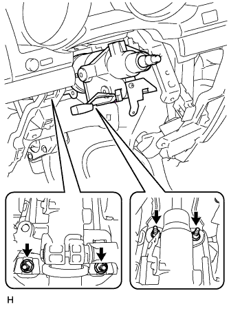
CONNECT NO. 2 STEERING INTERMEDIATE SHAFT
-
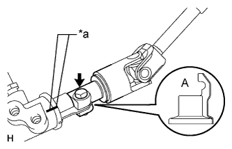
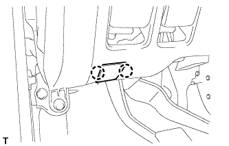
Text in Illustration *a Matchmark Align the part of the dust cover labeled A with the No. 2 steering intermediate shaft, and install the No. 2 steering intermediate shaft assembly to the steering link assembly.
-
Install the bolt.
- Torque:
- 35 N*m { 360 kgf*cm, 26 ft.*lbf }
Note
Be careful not to damage the dust cover.
-
-
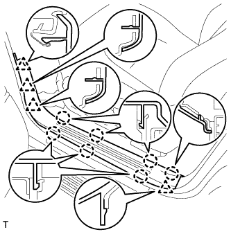
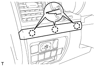
INSTALL STEERING COLUMN HOLE COVER SUB-ASSEMBLY
-
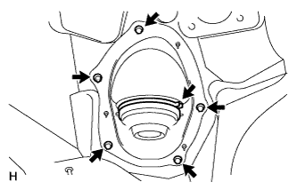
Install the 4 bolts and nut.
- Torque:
- 5.0 N*m { 51 kgf*cm, 44 in.*lbf }
Note
Do not fold back the boot part of the steering hole cover or extend it excessively. if it is extended excessively, return it to its original position.
Tech Tips
Install the steering intermediate shaft assembly from the inside of the vehicle.
-
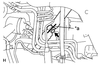
Using needle nose pliers, lock the clamp to the steering column hole cover to install it.
Note
Be careful when performing the operation as the clamp may not lock if the claws of the clamp are deformed.
-
-
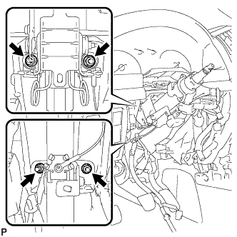
CONNECT STEERING INTERMEDIATE SHAFT ASSEMBLY
-
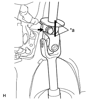
Text in Illustration *a Matchmark Align the matchmarks on the No. 2 steering intermediate shaft assembly and the steering intermediate shaft assembly.
Tech Tips
Install the steering intermediate shaft from the inside of the vehicle.
-
Install the bolt.
- Torque:
- 35 N*m { 360 kgf*cm, 26 ft.*lbf }
-
-
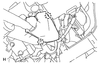
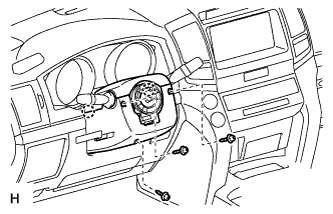
INSTALL STEERING COLUMN ASSEMBLY
-
Align the matchmarks on the steering intermediate shaft and the steering column.
-
Text in Illustration *a Matchmark Install the bolt.
- Torque:
- 35 N*m { 360 kgf*cm, 26 ft.*lbf }
-
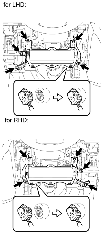
w/o Entry and Start System:
-
Install the steering column with the 4 nuts.
- Torque:
- 21 N*m { 214 kgf*cm, 15 ft.*lbf }
-
-
w/ Entry and Start System
-
Install the steering column with the 4 nuts.
- Torque:
- 26 N*m { 265 kgf*cm, 19 ft.*lbf }
-
-
-
INSTALL NO. 3 AIR DUCT SUB-ASSEMBLY
-
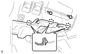
Attach the 2 claws to install the duct.
-
Install the clip.
-
-
INSTALL WIRE HARNESS PROTECTOR AND WIRE HARNESS
-
Attach the 2 claws to connect the wire harness protector and wire harness.
-
-
INSTALL DRIVER SIDE KNEE AIRBAG ASSEMBLY (w/ Driver Side Knee Airbag)
-
Connect the connector.
Note
When handling the airbag connector, take care not to damage the airbag wire harness.
-
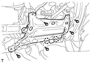
Install the driver side knee airbag with the 5 bolts.
- Torque:
- 10 N*m { 102 kgf*cm, 7 ft.*lbf }
-
-
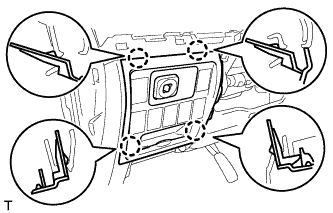
INSTALL LOWER INSTRUMENT PANEL SUB-ASSEMBLY (w/o Driver Side Knee Airbag)
-
Attach the 2 claws and connect the DLC3.
-
Install the lower instrument panel with the 5 bolts.
-
-
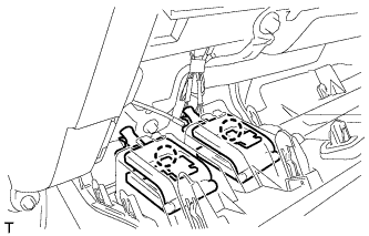
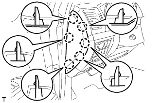
INSTALL NO. 1 SWITCH HOLE BASE
-
Connect the connectors.
-
Attach the 4 claws to install the No. 1 switch hole base.
-
-
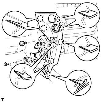
INSTALL LOWER NO. 1 INSTRUMENT PANEL FINISH PANEL
-
Connect the connectors.
-
for Automatic Air Conditioning System:
-
Attach the 2 claws to install the room temperature sensor.
-
-
Attach the 2 claws to connect the 2 control cables.
-
w/ Driver Side Knee Airbag:
-
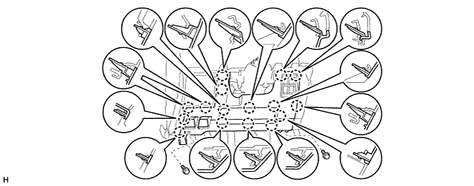
Attach the 16 claws to install the lower No. 1 instrument panel finish panel.
-
Install the 2 bolts.
-
-
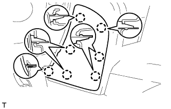
w/o Driver Side Knee Airbag:
-
Attach the 9 claws to install the lower No. 1 instrument panel finish panel.
-
Install the 2 bolts.
-
-
Attach the 2 claws to close the hole cover.
-
-
INSTALL COWL SIDE TRIM BOARD LH

-
Attach the 2 clips to install the cowl side trim board.
-
Install the cap nut.
-
-
INSTALL NO. 1 INSTRUMENT PANEL UNDER COVER SUB-ASSEMBLY (w/ Floor Under Cover)
-
Connect the connectors.
-
Attach the 3 claws to install the No. 1 instrument panel under cover.
-
Install the 2 screws.
-
-
INSTALL FRONT DOOR SCUFF PLATE LH
-
Attach the 7 claws and 4 clips to install the scuff plate.
-
-
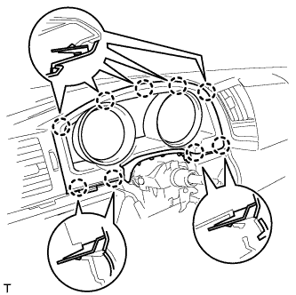
INSTALL INSTRUMENT CLUSTER FINISH PANEL SUB-ASSEMBLY (w/o Multi-information Display)
-
Attach the 9 claws to install the instrument cluster finish panel.
-
-
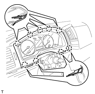
INSTALL INSTRUMENT CLUSTER FINISH PANEL SUB-ASSEMBLY (w/ Multi-information Display)
-
Connect the connector.
-
Attach the 9 claws to install the instrument cluster finish panel.
-
-
INSTALL NO. 2 INSTRUMENT CLUSTER FINISH PANEL GARNISH
-
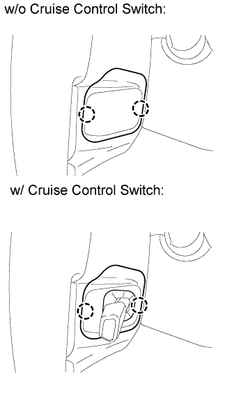
Attach the 2 claws to install the No. 2 instrument cluster finish panel garnish.
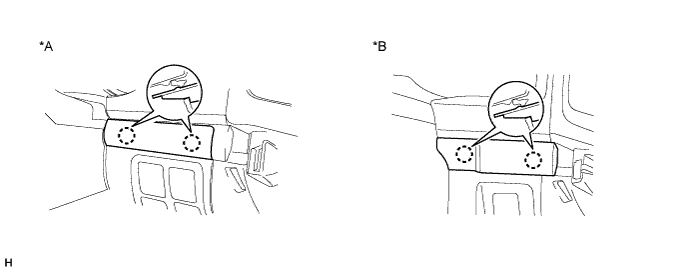
Text in Illustration *A w/ Entry and Start System *B w/o Entry and Start System
-
-
INSTALL NO. 1 INSTRUMENT CLUSTER FINISH PANEL GARNISH
-
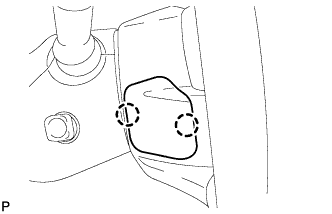
Attach the 3 claws to install the No. 1 instrument cluster finish panel garnish.
-
-
INSTALL INSTRUMENT SIDE PANEL LH
-
Attach the 6 claws to install the instrument side panel.
-
-
INSTALL LOWER INSTRUMENT PANEL PAD SUB-ASSEMBLY LH
-
Connect the connectors and attach the 2 clamps.
-
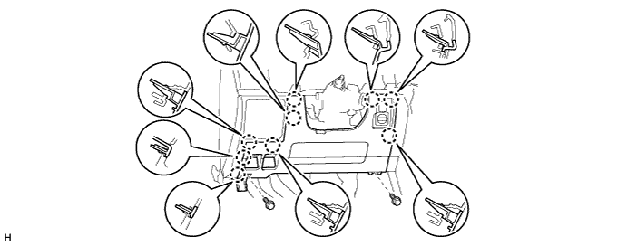
Attach the 8 claws to install the lower instrument panel pad sub-assembly.
-
Install the clip and screw.
-
-
INSTALL NO. 2 INSTRUMENT PANEL FINISH PANEL CUSHION
-
Attach the 7 claws to install the No. 2 instrument panel finish panel cushion.
-
-
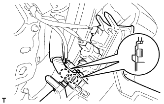
INSTALL COMBINATION SWITCH ASSEMBLY WITH SPIRAL CABLE SUB-ASSEMBLY
-
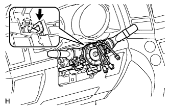
Using pliers, grip the claws of the clamp and install the combination switch assembly with spiral cable sub-assembly to the steering column assembly with the clamp.
-
Connect the connectors to the combination switch with spiral cable.
-
-
INSTALL UPPER STEERING COLUMN COVER
-
Attach the claw to install the upper steering column cover.
-
Attach the 4 clips to install the upper steering column cover onto the instrument cluster finish panel.
-
-
INSTALL LOWER STEERING COLUMN COVER
-
Attach the 2 claws to install the lower steering column cover.
Note
Do not damage the tilt and telescopic switch.
-
Install the 3 screws.
- Torque:
- 2.0 N*m { 20 kgf*cm, 18 in.*lbf }
-
-
INSTALL STEERING WHEEL ASSEMBLY
-
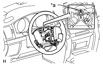
Text in Illustration *a Matchmark Align the matchmarks on the steering wheel assembly and steering main shaft assembly.
-
Install the steering wheel assembly set nut.
- Torque:
- 50 N*m { 510 kgf*cm, 37 ft.*lbf }
-
-
INSTALL STEERING PAD
-
Support the steering pad with one hand.
-
Connect the 2 connectors to the steering pad.
Note
When handling the airbag connector, take care not to damage the airbag wire harness.
-
Connect the horn connector.
-
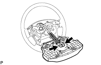
Confirm that the circumference groove of the "TORX" screw fits in the screw case, and place the steering pad onto the steering wheel.
-
Using a T30 "TORX" socket wrench, tighten the 2 screws.
- Torque:
- 8.8 N*m { 90 kgf*cm, 78 in.*lbf }
-
-
INSTALL LOWER NO. 2 STEERING WHEEL COVER
-
Attach the 2 claws to install the cover.
-
-
INSTALL LOWER NO. 3 STEERING WHEEL COVER
-
Attach the 2 claws to install the cover.
-
-
CHECK FRONT WHEELS FACING STRAIGHT AHEAD
-
INSTALL FRONT WHEELS
-
CONNECT CABLE TO NEGATIVE BATTERY TERMINAL
Note
When disconnecting the cable, some systems need to be initialized after the cable is reconnected Click here.
-
INSPECT SRS WARNING LIGHT
-
Inspect the SRS warning light Click here.
-