- Click here
INSTALL STEERING MAIN SHAFT ASSEMBLY (w/o Entry and Start System)
-
Install the steering main shaft assembly to the steering column upper tube.
-
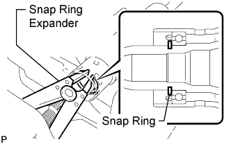
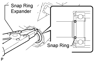
Using a snap ring expander, install a new shaft snap ring to the steering main shaft assembly.
Note:
-
Make sure the steering main shaft snap ring is securely installed to the groove.
-
Do not damage the steering main shaft assembly.
-
-
- Click here
INSTALL NO. 1 TILT STEERING SUPPORT COLLAR (w/o Entry and Start System)
-
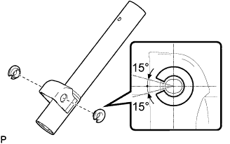
Install the 2 No. 1 tilt steering support collars to the steering lower column tube assembly.
Note:When installing the No. 1 tilt steering support collar, make sure that the cutout portion is aligned as shown in the illustration.
-
- Click here
INSTALL STEERING COLUMN BRACKET SPACER (w/o Entry and Start System)
-
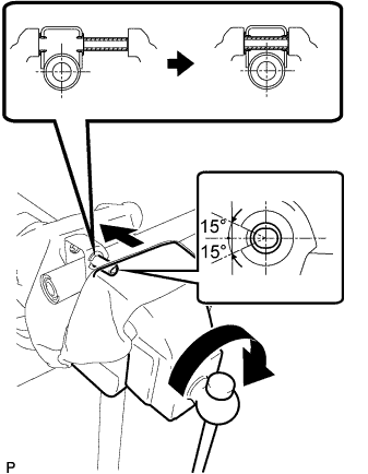
Clamp the steering column bracket spacer and steering lower column tube assembly in a vise between a cloth and aluminum plates, and install the steering column bracket spacer to the steering lower column tube assembly using the vise.
Note:When installing the steering column bracket spacer, make sure that it is positioned so that the inner diameter is as shown in the illustration.
-
- Click here
INSTALL TELESCOPIC STEERING GUIDE (w/o Entry and Start System)
-
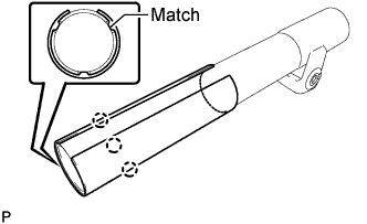
Align the 3 protrusions of the telescopic steering guide with the 3 holes of the steering lower column tube assembly and install the telescopic steering guide.
-
- Click here
INSTALL STEERING LOWER COLUMN TUBE ASSEMBLY (w/o Entry and Start System)
-
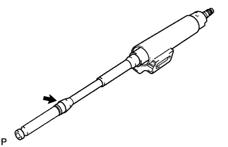
Apply MP grease to the area of the steering main shaft assembly indicated by the arrow in the illustration.
-
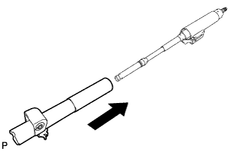
Install the steering lower column tube assembly to the steering column upper tube.
-
- Click here
INSTALL TILT STEERING SUPPORT (w/o Entry and Start System)
-
Install the tilt steering support with the bolt.
15 N*m 153 kgf*cm 11 ft.*lbf
-
- Click here
INSTALL NO. 1 STEERING COLUMN RING (w/o Entry and Start System)
-
Using a snap ring expander, install a new No. 1 steering column ring to the steering main shaft.
Note:
-
Make sure the No. 1 steering column ring is securely installed to the groove.
-
Do not damage the steering main shaft assembly.
-
-
- Click here
INSTALL TILT STEERING PAWL ASSEMBLY (w/o Entry and Start System)
-
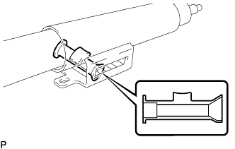
Install the tilt steering pawl assembly to the steering column upper tube.
Note:When installing the tilt steering pawl assembly, position the opening as shown in the illustration.
-
- Click here
INSTALL BREAK AWAY BRACKET (w/o Entry and Start System)
-
Apply MP grease to the sliding areas of a new break away bracket and install it to the steering column upper tube.
-
- Click here
INSTALL STEERING COLUMN TUBE STOPPER (w/o Entry and Start System)
-
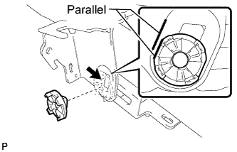
Apply MP grease to the sliding surface of the steering column tube stopper (the one with the groove) and install it to the break away bracket.
Note:Align the flat edge of the steering column tube stopper and the raised sliding area of the break away bracket as shown in the illustration.
-
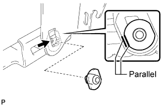
Apply MP grease to the sliding surface of the steering column tube stopper (the one without the groove) and install it to the break away bracket.
Note:Align the flat edge of the steering column tube stopper and the raised sliding area of the break away bracket as shown in the illustration.
-
- Click here
INSTALL NO. 1 TILT LEVER LOCK BOLT (w/o Entry and Start System)
-
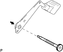
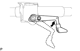
Apply MP grease to the sliding surface of the steering tilt lever and install it to the No. 1 tilt lever lock bolt.
-
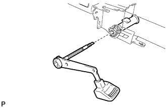
Install the No. 1 tilt lever lock bolt to the break away bracket.
Note:
-
Do not drop the steering column tube stopper.
-
Pass the No. 1 tilt lever lock bolt through the hole of the tilt steering pawl assembly.
-
-
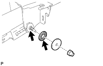
Apply MP grease to the sliding surface of the thrust needle roller bearing and install it to the No. 1 tilt lever lock bolt.
-
Temporarily install the tilt steering rotor to the No. 1 tilt lever lock bolt with a new No. 1 tilt steering adjusting nut.
-

Using an 8 mm socket hexagon wrench, tighten the No. 1 tilt lever lock bolt.
2.0 N*m 20 kgf*cm 18 in.*lbf Note:The tightening direction for the No. 1 tilt lever lock bolt is the tightening direction for bolts with a left-handed thread.
-
- Click here
INSTALL NO. 1 TILT STEERING SUPPORT REINFORCEMENT (w/o Entry and Start System)
-
Install the No. 1 tilt steering support reinforcement to the steering tilt lever with the steering tilt lever bolt.
5.4 N*m 55 kgf*cm 48 in.*lbf Note:The tightening direction for the steering tilt lever bolt is the tightening direction for bolts with a left-handed thread.
-
- Click here
TIGHTEN NO. 1 TILT STEERING ADJUSTING NUT (w/o Entry and Start System)
-
Lock the steering tilt lever.
-
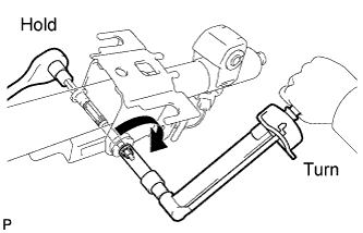
Using an 8 mm socket hexagon wrench, hold the No. 1 tilt lever lock bolt in place and tighten the No. 1 tilt steering adjusting nut.
3.0 N*m 31 kgf*cm 27 in.*lbf -
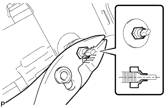
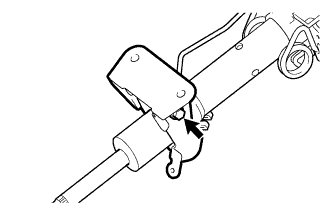
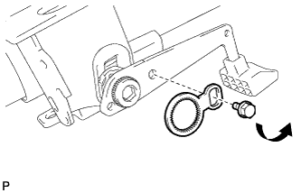
Using pliers, stake the No. 1 tilt steering adjusting nut as shown in the illustration.
Note:After staking the No. 1 tilt steering adjusting nut, make sure it is not loose.
-
- Click here
INSTALL TILT STEERING JUMP UP SPRING (w/o Entry and Start System)
-
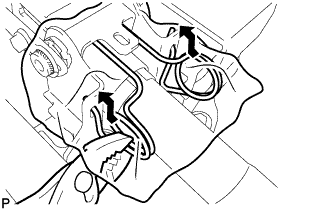
Using pliers, move the tilt steering jump up spring in the direction indicated by the arrow in the illustration to install it to the break away bracket.
Note:To avoid spatter, cover the area with a cloth.
-
- Click here
INSTALL TILT LEVER RETURN SPRING (w/o Entry and Start System)
-
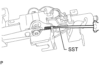
Using SST, install the tilt lever return spring to the break away bracket and steering tilt lever.
09921-00010 Note:
-
To avoid spatter, cover the area with a cloth.
-
Do not let the damper fall off of the tilt lever return spring.
-
-
- Click here
INSTALL TILT STEERING SUPPORT BOND CABLE (w/o Entry and Start System)
-
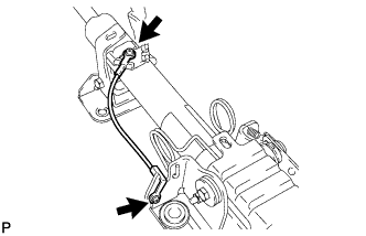
Install the steering support bond cable to the steering column with the 2 screws.
-
- Click here
INSTALL BREAK AWAY COLLAR SUB-ASSEMBLY (w/o Entry and Start System)
-
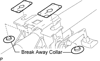
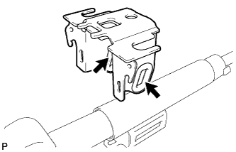
Install the 2 new break away collars and 2 new break away capsules to the break away bracket.
Note:Do not compress the disc spring portion of the break away collar.
-
- Click here
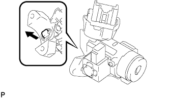
INSTALL IGNITION OR STARTER SWITCH ASSEMBLY (w/o Entry and Start System)
-
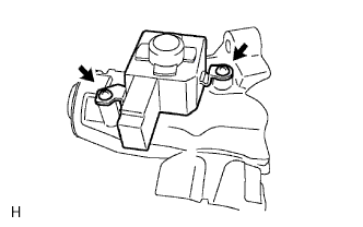
Attach the 2 claws to install the ignition or starter switch assembly to the steering column upper bracket assembly.
-
- Click here
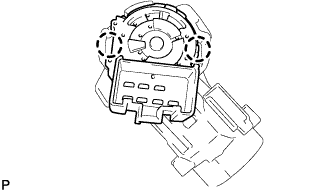
INSTALL UNLOCK WARNING SWITCH ASSEMBLY (w/o Entry and Start System)
-
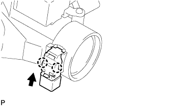
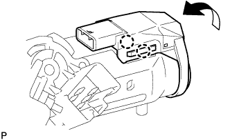
Attach the 2 claws to install the unlock warning switch assembly to the steering column upper bracket assembly.
Tip:Move the unlock warning switch assembly in the direction indicated by the arrow in the illustration to install it.
-
- Click here
INSTALL IGNITION SWITCH LOCK CYLINDER ASSEMBLY (w/o Entry and Start System)
-
Turn the ignition switch lock cylinder assembly to ACC.
-
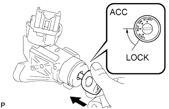
Insert the ignition switch lock cylinder assembly into the steering column upper bracket assembly to install it.
-
Check that the ignition switch lock cylinder assembly is securely fixed in place.
-
- Click here
INSPECT STEERING LOCK OPERATION (w/o Entry and Start System)
-
Remove the key and check that the steering lock operates.
-
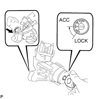
Insert the key, turn the ignition switch to ACC and check that the steering lock disengages.
-
- Click here
INSTALL STEERING COLUMN UPPER WITH SWITCH BRACKET ASSEMBLY (w/o Entry and Start System)
-
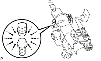
Install the steering column upper with switch bracket assembly and steering column upper clamp with 2 new steering lock set bolts, and tighten the bolts until the heads break off.
-
- Click here
INSTALL TRANSPONDER KEY AMPLIFIER (w/o Entry and Start System)
-
Attach the 2 claws to install the transponder key amplifier to the steering column upper with switch bracket assembly.
-
- Click here
INSTALL KEY INTERLOCK SOLENOID (for Automatic Transmission)
-
Install the key interlock solenoid to the steering column upper bracket with the 2 screws.
-
-
Click here
INSTALL STEERING LOCK ACTUATOR ASSEMBLY (w/ Entry and Start System)
-
Temporarily install the steering lock actuator assembly with 2 new tapered-head bolts.
-
Tighten the 2 tapered-head bolts until the bolt heads break off.
-