STEERING COLUMN ASSEMBLY (for Manual Tilt and Manual Telescopic Steering Column) DISASSEMBLY

Note
When using a vise, do not overtighten it.
-
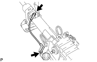
REMOVE STEERING LOCK ACTUATOR ASSEMBLY (w/ Entry and Start System)
-
Using a center punch, mark the center of the 2 tapered-head bolts.
-
Using a 3 to 4 mm (0.118 to 0.157 in.) drill, drill a hole in the 2 bolts.
-
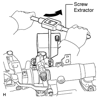
Using a screw extractor, remove the 2 bolts and the steering lock actuator assembly from the steering column assembly.
-
-
REMOVE KEY INTERLOCK SOLENOID (for Automatic Transmission)
-
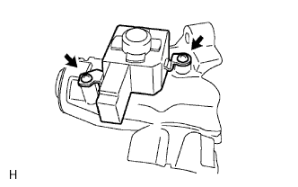
Remove the 2 screws and solenoid from the steering column upper bracket.
-
-
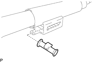
REMOVE TRANSPONDER KEY AMPLIFIER (w/o Entry and Start System)
-
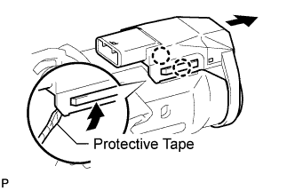
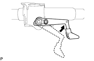
Detach the 2 claws, slide the transponder key amplifier in the direction indicated by the arrow in the illustration and remove it from the steering column upper with switch bracket assembly.
-
-
REMOVE STEERING COLUMN UPPER WITH SWITCH BRACKET ASSEMBLY (w/o Entry and Start System)
-
Using a drill, drill a hole to insert a screw extractor into each steering lock bolt.
-
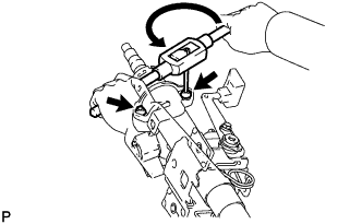
Using a screw extractor, remove the 2 steering lock bolts, steering column upper with switch bracket and steering column upper clamp.
-
-
REMOVE IGNITION SWITCH LOCK CYLINDER ASSEMBLY (w/o Entry and Start System)
-
Turn the ignition switch lock cylinder assembly to ACC.
-
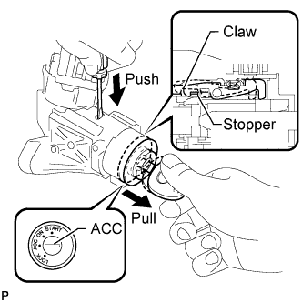
Insert a thin-bladed screwdriver into the hole of the steering column upper bracket assembly as shown in the illustration and pull out the key until the claw of the ignition switch lock cylinder assembly contacts the stopper of the steering column upper bracket assembly.
Note
Be sure to pull out the key until the claw firmly contacts the stopper. There will be problems later if the key is not pulled out until the claw of the ignition switch lock cylinder assembly contacts the stopper of the steering column upper bracket assembly.
-
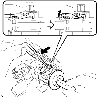
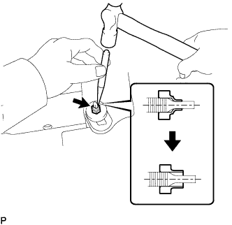
Insert a thin-bladed screwdriver into the hole of the steering column upper bracket assembly as shown in the illustration, push the thin-bladed screwdriver in the direction shown in the illustration to detach the claw and pull out the ignition switch lock cylinder assembly.
-
-
REMOVE UNLOCK WARNING SWITCH ASSEMBLY (w/o Entry and Start System)
-
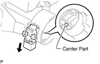
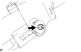
Push up the center part of the unlock warning switch assembly, detach the 2 claws and remove the unlock warning switch assembly.
Tech Tips
Slide the unlock warning switch assembly in the direction indicated by the arrow in the illustration to remove it.
-
-
REMOVE IGNITION OR STARTER SWITCH ASSEMBLY (w/o Entry and Start System)
-
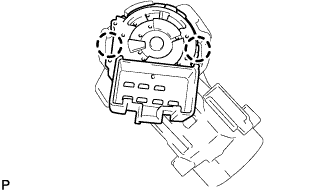
Detach the 2 claws and remove the ignition or starter switch assembly from the steering column upper bracket assembly.
-
-
REMOVE TILT STEERING SUPPORT BOND CABLE (w/o Entry and Start System)
-
Remove the 2 screws and tilt steering support bond cable.
-
-
REMOVE BREAK AWAY COLLAR SUB-ASSEMBLY (w/o Entry and Start System)
-
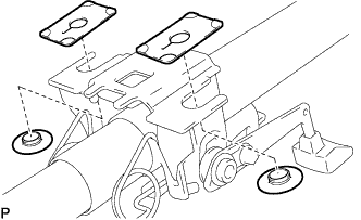
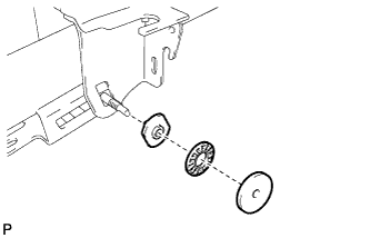
Remove the 2 break away collars and 2 break away capsules from the break away bracket.
-
-
REMOVE TILT LEVER RETURN SPRING (w/o Entry and Start System)
-
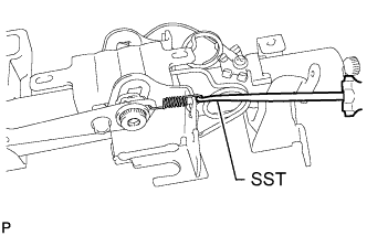
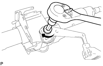
Using SST, remove the tilt lever return spring from the break away bracket and steering tilt lever.
- SST
- 09921-00010
Tech Tips
To avoid spatter, cover the area with a cloth.
Note
Do not let the damper fall off of the tilt lever return spring.
-
-
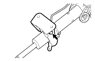
REMOVE TILT STEERING JUMP UP SPRING (w/o Entry and Start System)
-
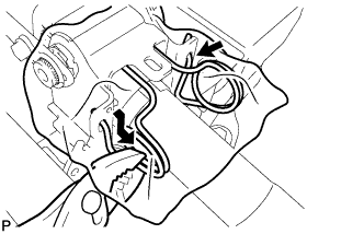
Using pliers, pull the tilt steering jump up spring in the direction indicated by the arrow in the illustration and remove it from the break away bracket.
Tech Tips
To avoid spatter, cover the area with a cloth.
-
-
LOOSEN NO. 1 TILT STEERING ADJUSTING NUT (w/o Entry and Start System)
-
Lock the steering tilt lever.
-
Using a hammer and chisel, loosen the staked part of the No. 1 tilt steering adjusting nut.
-
Loosen the No. 1 tilt steering adjusting nut.
Note
Be sure to only loosen the No. 1 tilt steering adjusting nut. Do not remove it.
-
-
REMOVE NO. 1 TILT STEERING SUPPORT REINFORCEMENT (w/o Entry and Start System)
-
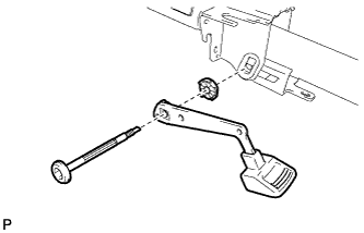
Remove the steering tilt lever bolt and No. 1 tilt steering support reinforcement from the steering tilt lever.
Note
The steering tilt lever bolt has a left-handed thread.
-
-
REMOVE NO. 1 TILT LEVER LOCK BOLT (w/o Entry and Start System)
-
Using an 8 mm socket hexagon wrench, loosen the No. 1 tilt lever lock bolt until it can be turned by hand.
Note
The loosening direction for the No. 1 tilt lever lock bolt is the loosening direction for bolts with a left-handed thread.
-
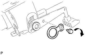
Remove the No. 1 tilt steering adjusting nut from the No. 1 tilt lever lock bolt.
-
Remove the tilt steering rotor, thrust needle roller bearing and steering column tube stopper from the No. 1 tilt lever lock bolt.
-
Remove the No. 1 tilt lever lock bolt, steering tilt lever and steering column tube stopper from the break away bracket.
-
-
REMOVE BREAK AWAY BRACKET (w/o Entry and Start System)
-
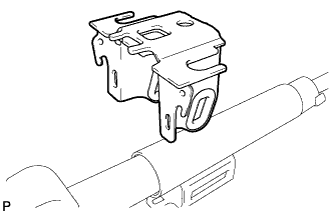
Remove the break away bracket from the steering column upper tube.
-
-
REMOVE TILT STEERING PAWL ASSEMBLY (w/o Entry and Start System)
-
Remove the tilt steering pawl assembly from the steering column upper tube.
-
-
REMOVE NO. 1 STEERING COLUMN RING (w/o Entry and Start System)
-
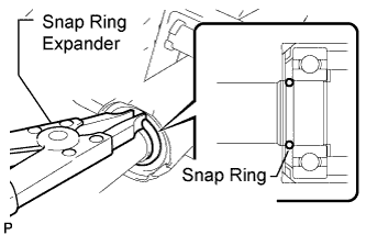
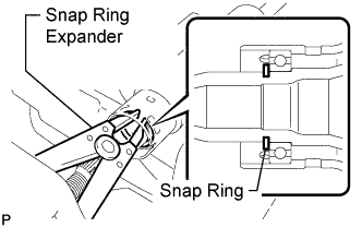
Using a snap ring expander, remove the shaft snap ring from the steering main shaft assembly.
Note
Do not damage the steering main shaft assembly.
-
-
REMOVE TILT STEERING SUPPORT (w/o Entry and Start System)
-
Remove the bolt and tilt steering support.
-
-
REMOVE STEERING LOWER COLUMN TUBE ASSEMBLY (w/o Entry and Start System)
-
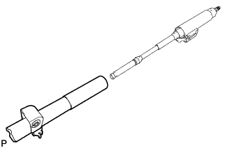
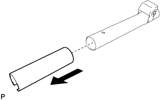
Remove the steering column lower tube assembly from the steering column upper tube.
-
-
REMOVE TELESCOPIC STEERING GUIDE (w/o Entry and Start System)
-
Remove the telescopic steering guide from the steering lower column tube assembly.
-
-
REMOVE STEERING COLUMN BRACKET SPACER (w/o Entry and Start System)
-
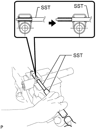
Using SST and a hammer, tap out the steering column bracket spacer from the steering lower column tube assembly.
- SST
- 09201-10000 ( 09201-01080 )
- 09950-70010 ( 09951-07100 )
-
-
REMOVE NO. 1 TILT STEERING SUPPORT COLLAR (w/o Entry and Start System)
-
Remove the 2 No. 1 tilt steering support collars from the steering lower column tube assembly.
-
-
REMOVE STEERING MAIN SHAFT ASSEMBLY (w/o Entry and Start System)
-
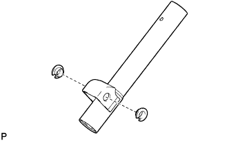
Using a snap ring expander, remove the shaft snap ring from the steering main shaft assembly.
Note
Do not damage the steering main shaft assembly.
-
Remove the steering main shaft assembly from the steering column upper tube.
-