- Click here
HANDLING PRECAUTIONS FOR STEERING ACTUATOR ASSEMBLY
Note:
-
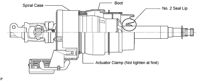
Be careful that the No. 2 seal lip or boot does not turn outward while carrying or installing the steering actuator assembly. If installing a new steering actuator assembly, make sure that the spiral center lock pin is securely inserted.
-
Do not use the steering actuator assembly if it has been dropped.
-
- Click here
INSTALL STEERING ACTUATOR ASSEMBLY
-
Make sure that the power steering link assembly is centered.
-
Install the steering actuator assembly.
-
If installing a new steering actuator assembly:
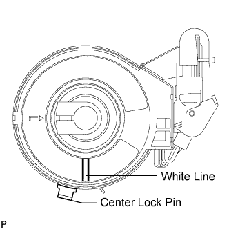
Install the steering actuator assembly with the white paint on the upper surface of the spiral case facing down.
Note:Do not pull out the center lock pin.
-
If reinstalling the removed steering actuator assembly:
-
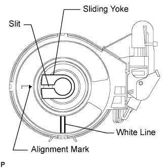
Slowly turn the spiral case clockwise until it locks.
-
Turn the spiral case two turns counterclockwise from the lock position.
-
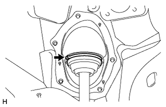
Align the slit of the sliding yoke with the alignment mark (▲).
-
Install the steering actuator assembly with the white paint on the upper surface of the spiral case facing down.
-
-
-
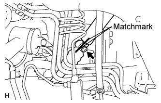
Align the matchmarks on the No. 2 steering intermediate shaft and steering actuator.
Note:
-
Do not fold back the boot part of the steering hole cover or turn it excessively. If it is turned excessively, return it to its original position.
-
Do not turn the actuator body and the spiral case.
Tip:Install the steering actuator from the inside of the vehicle.
-
-
Install the bolt.
35 N*m 360 kgf*cm 26 ft.*lbf -
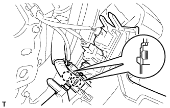
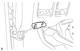
Using needle nose pliers, lock the clamp to the steering column hole cover to install it.
Note:Be careful when performing the operation as the clamp may not lock if the claws of the clamp are deformed.
-
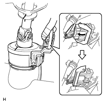
Move the lock in the direction of the arrow and connect the steering actuator connector.
Tip:When a new actuator is installed, remove the center lock pin.
-
Connect the connector.
-
-
Click here
INSTALL STEERING COLUMN ASSEMBLY
-
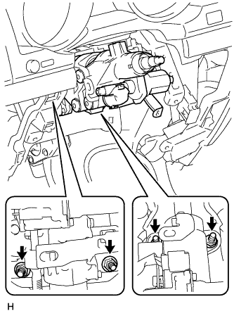
Align the matchmarks on the steering actuator and steering column.
-
Install the bolt.
35 N*m 360 kgf*cm 26 ft.*lbf -
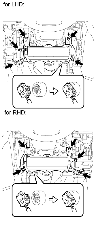
Install the steering column with the 4 nuts.
26 N*m 265 kgf*cm 19 ft.*lbf
-
- Click here
INSTALL NO. 3 AIR DUCT SUB-ASSEMBLY
-
Attach the 2 claws to install the duct.
-
Install the clip.
-
-
Click here
CONNECT WIRE HARNESS PROTECTOR AND WIRE HARNESS
-
Attach the 3 claws to connect the wire harness protector and wire harness.
-
- Click here
INSTALL DRIVER SIDE KNEE AIRBAG ASSEMBLY (w/ Driver Side Knee Airbag)
-
Connect the connector.
Note:When handling the airbag connector, take care not to damage the airbag wire harness.
-
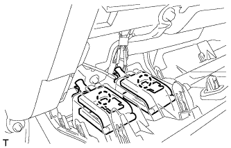
Install the driver side knee airbag with the 5 bolts.
10 N*m 102 kgf*cm 7 ft.*lbf
-
-
Click here
INSTALL LOWER INSTRUMENT PANEL SUB-ASSEMBLY (w/o Driver Side Knee Airbag)
-
Attach the 2 claws and connect the DLC3.
-
Install the lower instrument panel with the 5 bolts.
-
-
Click here
INSTALL NO. 1 SWITCH HOLE BASE
-
Connect the connectors.
-
Attach the 4 claws to install the No. 1 switch hole base.
-
- Click here
INSTALL LOWER NO. 1 INSTRUMENT PANEL FINISH PANEL
-
Connect the connectors.
-
for Automatic Air Conditioning System:
-
Attach the 2 claws to install the room temperature sensor.
-
-
Attach the 2 claws to connect the 2 control cables.
-
w/ Driver Side Knee Airbag:
-
Attach the 16 claws to install the lower No. 1 instrument panel finish panel.
-
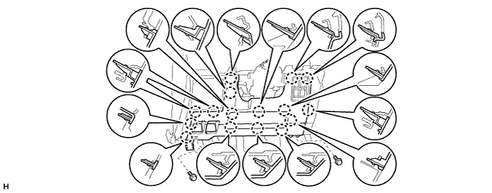
Install the 2 bolts.
-
-
w/o Driver Side Knee Airbag:
-
Attach the 9 claws to install the lower No. 1 instrument panel finish panel.
-
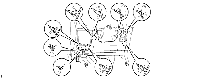
Install the 2 bolts.
-
-
Attach the 2 claws to close the hole cover.
-
-
Click here
INSTALL COWL SIDE TRIM BOARD LH
-
Attach the 2 clips to install the cowl side trim board.
-
Install the cap nut.
-
-
Click here
INSTALL NO. 1 INSTRUMENT PANEL UNDER COVER SUB-ASSEMBLY (w/ Floor Under Cover)
-
Connect the connectors.
-
Attach the 3 claws to install the No. 1 instrument panel under cover.
-
Install the 2 screws.
-
-
Click here
INSTALL FRONT DOOR SCUFF PLATE LH
-
Attach the 7 claws and 4 clips to install the scuff plate.
-
-
Click here
INSTALL INSTRUMENT CLUSTER FINISH PANEL SUB-ASSEMBLY (w/o Multi-information Display)
-
Attach the 9 claws to install the instrument cluster finish panel.
-
-
Click here
INSTALL INSTRUMENT CLUSTER FINISH PANEL SUB-ASSEMBLY (w/ Multi-information Display)
-
Connect the connector.
-
Attach the 9 claws to install the instrument cluster finish panel.
-
- Click here
INSTALL NO. 2 INSTRUMENT CLUSTER FINISH PANEL GARNISH
-
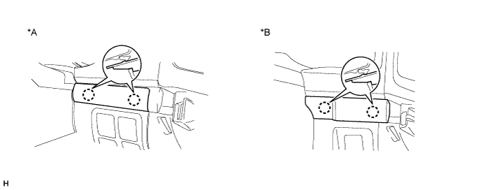
Attach the 2 claws to install the No. 2 instrument cluster finish panel garnish.
Table 1. Text in Illustration *A w/ Entry and Start System *B w/o Entry and Start System
-
-
Click here
INSTALL NO. 1 INSTRUMENT CLUSTER FINISH PANEL GARNISH
-
Attach the 3 claws to install the No. 1 instrument cluster finish panel garnish.
-
-
Click here
INSTALL INSTRUMENT SIDE PANEL LH
-
Attach the 6 claws to install the instrument side panel.
-
-
Click here
INSTALL LOWER INSTRUMENT PANEL PAD SUB-ASSEMBLY LH
-
Connect the connectors and attach the 2 clamps.
-
Attach the 8 claws to install the lower instrument panel pad sub-assembly.
-
Install the clip and screw.
-
-
Click here
INSTALL NO. 2 INSTRUMENT PANEL FINISH PANEL CUSHION
-
Attach the 7 claws to install the No. 2 instrument panel finish panel cushion.
-
-
Click here
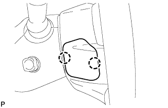
INSTALL COMBINATION SWITCH ASSEMBLY WITH SPIRAL CABLE SUB-ASSEMBLY
-
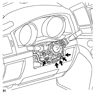
Using pliers, grip the claws of the clamp and install the combination signal switch assembly with spiral cable sub-assembly to the steering column assembly with the clamp.
-
Connect the 5 connectors to the combination switch with spiral cable.
-
-
Click here
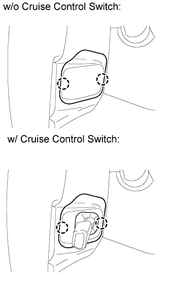
INSTALL TILT AND TELESCOPIC SWITCH
-
Attach the claw to install the switch.
-
Connect the switch connector.
-
-
Click here
INSTALL UPPER STEERING COLUMN COVER
-
Attach the claw to install the upper steering column cover.
-
Attach the 4 clips to the instrument cluster finish panel.
-
-
Click here
INSTALL LOWER STEERING COLUMN COVER
-
Attach the 2 claws to install the lower steering column cover.
Note:Do not damage the tilt and telescopic switch.
-
Install the 3 screws.
1.5 N*m 15 kgf*cm 13 in.*lbf
-
- Click here
INSTALL STEERING WHEEL ASSEMBLY
-
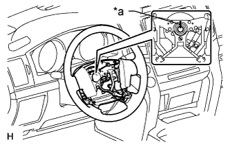
Align the matchmarks on the steering wheel assembly and steering main shaft assembly.
Table 2. Text in Illustration *a Matchmark -
Install the steering wheel assembly set nut.
50 N*m 510 kgf*cm 37 ft.*lbf
-
- Click here
INSTALL STEERING PAD
-
Support the steering pad with one hand.
-
Connect the 2 connectors to the steering pad.
Note:When handling the airbag connector, take care not to damage the airbag wire harness.
-
Connect the horn connector.
-
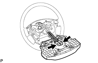
Confirm that the circumference groove of the "TORX" screw fits in the screw case, and place the steering pad onto the steering wheel.
-
Using a T30 "TORX" socket wrench, tighten the 2 screws.
8.8 N*m 90 kgf*cm 78 in.*lbf
-
- Click here
INSTALL LOWER NO. 2 STEERING WHEEL COVER
-
Attach the 2 claws to install the cover.
-
- Click here
INSTALL LOWER NO. 3 STEERING WHEEL COVER
-
Attach the 2 claws to install the cover.
-
- Click here
CONNECT CABLE TO NEGATIVE BATTERY TERMINAL
Note:
-
Reset the AUTO TILT AWAY function setting to the previous condition by changing the customize parameter (Click here).
-
When disconnecting the cable, some systems need to be initialized after the cable is reconnected (Click here).
-
- Click here
INSPECT SRS WARNING LIGHT
-
Inspect the SRS warning light (Click here).
-
- Click here
PERFORM VARIABLE GEAR RATIO STEERING SYSTEM CALIBRATION
-
Perform variable gear ratio steering system calibration (Click here).
-