STEERING CONTROL ECU (for LHD) REMOVAL

-
DISCONNECT CABLE FROM NEGATIVE BATTERY TERMINAL
CAUTION:
Wait at least 90 seconds after disconnecting the cable from the negative (-) battery terminal to disable the SRS system.
Note
-
After the engine switch is turned off, the navigation system requires approximately 90 seconds to record various types of memory and settings. As a result, after turning the engine switch off, wait 90 seconds or more before disconnecting the cable from the negative (-) battery terminal.
-
When disconnecting the cable, some systems need to be initialized after the cable is reconnected Click here.
-
-
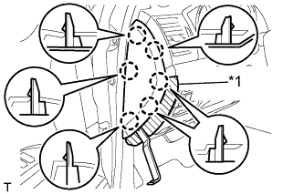
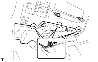
REMOVE NO. 2 INSTRUMENT PANEL FINISH PANEL CUSHION
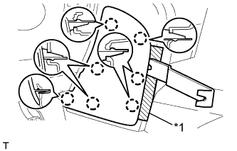
Text in Illustration *1 Protective Tape
-
Put protective tape around the No. 2 instrument panel finish panel cushion.
-
Using a moulding remover, detach the 7 claws and remove the No. 2 instrument panel finish panel cushion.
-
-
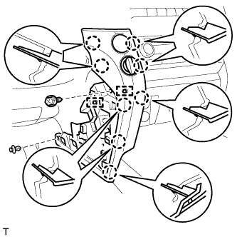
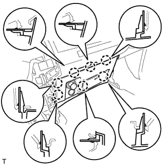
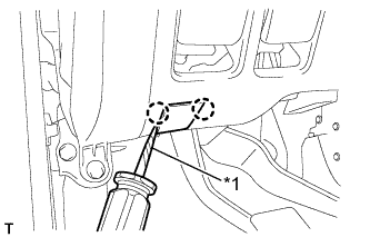
REMOVE LOWER INSTRUMENT PANEL PAD SUB-ASSEMBLY LH
-
Remove the clip and screw.
-
Detach the 8 claws.
-
Disconnect the connectors, detach the 2 clamps and remove the lower instrument panel pad sub-assembly.
-
-
REMOVE NO. 1 INSTRUMENT PANEL FINISH PANEL CUSHION
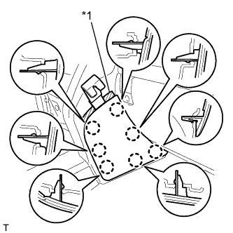
Text in Illustration *1 Protective Tape
-
Put protective tape around the No. 1 instrument panel finish panel cushion.
-
Using a moulding remover, detach the 7 claws and remove the No. 1 instrument panel finish panel cushion.
-
-
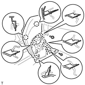
REMOVE LOWER INSTRUMENT PANEL PAD SUB-ASSEMBLY RH
-
Remove the clip and screw.
-
Detach the 7 claws and remove the lower instrument panel pad sub-assembly.
-
-
REMOVE LOWER CENTER INSTRUMENT CLUSTER FINISH PANEL SUB-ASSEMBLY
-
Detach the 7 claws.
-
Disconnect the connectors and remove the lower center instrument cluster finish panel sub-assembly.
-
-
REMOVE INSTRUMENT SIDE PANEL LH
Text in Illustration *1 Protective Tape
-
Place protective tape as shown in the illustration.
-
Using a moulding remover, detach the 6 claws and remove the instrument side panel.
-
-
REMOVE NO. 1 INSTRUMENT CLUSTER FINISH PANEL GARNISH
Text in Illustration *1 Protective Tape
-
Place protective tape as shown in the illustration.
-
Using a moulding remover, detach the 3 claws and remove the No. 1 instrument cluster finish panel garnish.
-
-
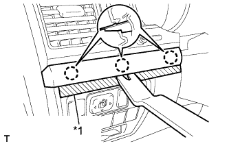
REMOVE NO. 2 INSTRUMENT CLUSTER FINISH PANEL GARNISH
-
Place protective tape as shown in the illustration.
-
Using a moulding remover, detach the 2 claws and remove the No. 2 instrument cluster finish panel garnish.
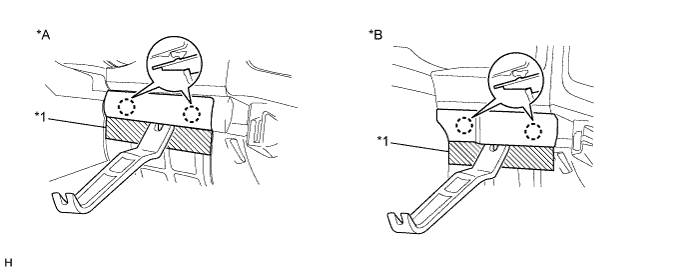
Text in Illustration *A w/ Entry and Start System *B w/o Entry and Start System *1 Protective Tape - -
-
-
REMOVE FRONT DOOR SCUFF PLATE LH
Tech Tips
Use the same procedures described for the LH side.
-
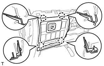
REMOVE NO. 1 INSTRUMENT PANEL UNDER COVER SUB-ASSEMBLY (w/ Floor Under Cover)
-
Remove the 2 screws.
-
Detach the 3 claws.
-
Disconnect the connectors and remove the No. 1 instrument panel under cover.
-
-
REMOVE COWL SIDE TRIM BOARD LH

-
Remove the cap nut.
-
Detach the 2 clips and remove the cowl side trim board.
-
-
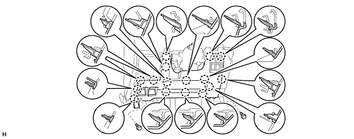
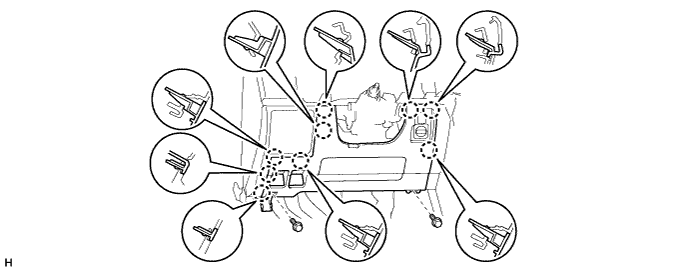
REMOVE LOWER NO. 1 INSTRUMENT PANEL FINISH PANEL
-
Using a screwdriver, detach the 2 claws and open the hole cover.
Tech Tips
Tape the screwdriver tip before use.
Text in Illustration *1 Protective Tape -
w/ Driver Side Knee Airbag:
-
Remove the 2 bolts.
-
Detach the 16 claws.
-
-
w/o Driver Side Knee Airbag:
-
Remove the 2 bolts.
-
Detach the 9 claws.
-
-
for Automatic Air Conditioning System:
-
Detach the 2 claws and remove the room temperature sensor.
-
-
Detach the 2 claws and disconnect the 2 control cables.
-
Disconnect the connectors and remove the lower No. 1 instrument panel finish panel.
-
-
REMOVE NO. 1 SWITCH HOLE BASE
-
Detach the 4 claws.
-
Disconnect the connectors and remove the No. 1 switch hole cover.
-
-
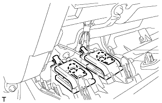
REMOVE DRIVER SIDE KNEE AIRBAG ASSEMBLY (w/ Driver Side Knee Airbag)
-
Remove the 5 bolts and driver side knee airbag.
-
Disconnect the connector.
Note
When handling the airbag connector, take care not to damage the airbag wire harness.
-
-
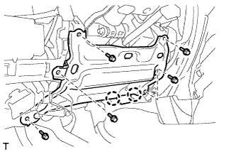
REMOVE LOWER INSTRUMENT PANEL SUB-ASSEMBLY (w/o Driver Side Knee Airbag)
-
Detach the 2 claws and disconnect the DLC3.
-
Remove the 5 bolts and lower instrument panel.
-
-
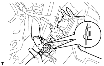
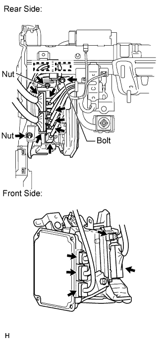
REMOVE STEERING CONTROL ECU WITH JUNCTION BLOCK
-
Rear Side:
-
Disconnect the 7 connectors.
-
Detach the 2 clamps.
-
Remove the bolt and 2 nuts.
-
-
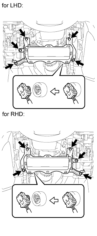
Front Side:
-
Disconnect the 5 connectors.
-
-
Remove the steering control ECU with junction block.
-
-
REMOVE STEERING CONTROL ECU
-
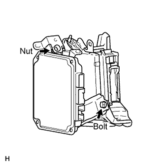
Remove the bolt, nut and steering control ECU from the junction block.
-