-
Click here
INSTALL AIR CONDITIONER PRESSURE SENSOR
-
Sufficiently apply compressor oil to a new O-ring and the fitting surface of the pressure sensor.
Compressor oil ND-OIL 8 or equivalent -
Install O-ring on the pressure switch.
-
Install the pressure sensor.
10.8 N*m 110 kgf*cm 8 ft.*lbf -
Connect the connector.
-
- Click here
CHARGE REFRIGERANT
09985-20010 09985-02130 09985-02150 09985-02090 09985-02110 09985-02010 09985-02050 09985-02060 09985-02070
-
Perform vacuum purging using a vacuum pump.
-

Charge refrigerant HFC-134a (R134a).
Table 1. Standard: Condenser Core Thickness Air Conditioning Type Cool Box Refrigerant Charging Amount 22 mm (0.866 in.) w/o Rear Cooler w/ Cool Box 870 +/-30 g (30.7 +/-1.1 oz.) w/o Cool Box 870 +/-30 g (30.7 +/-1.1 oz.) w/ Rear Cooler w/ Cool Box 1010 +/-30 g (35.6 +/-1.1 oz.) w/o Cool Box 960 +/-30 g (33.9 +/-1.1 oz.) 16 mm (0.630 in.) w/o Rear Cooler w/ Cool Box 770 +/-30 g (27.2 +/-1.1 oz.) w/o Cool Box 770 +/-30 g (27.2 +/-1.1 oz.) w/ Rear Cooler w/ Cool Box 970 +/-30 g (34.2 +/-1.1 oz.) w/o Cool Box 920 +/-30 g (32.5 +/-1.1 oz.) Note:
-
Do not operate the cooler compressor before charging refrigerant as the cooler compressor will not work properly without any refrigerant, and will overheat.
-
Approximately 200 g (7.05 oz.) of refrigerant may need to be charged after bubbles disappear. The refrigerant amount should be checked by measuring its quantity, and not with the sight glass.
-
-
- Click here
WARM UP ENGINE
-
Warm up the engine at less than 1850 rpm for 2 minutes or more after charging the refrigerant.
Note:Be sure to warm up the compressor when turning the A/C switch is on after removing and installing the cooler refrigerant lines (including the compressor), to prevent damage to the compressor.
-
- Click here
CHECK REFRIGERANT GAS LEAK
-
After recharging the refrigerant gas, check for refrigerant gas leakage using a halogen leak detector.
-
Perform the operation under these conditions:
-
Stop the engine.
-
Secure good ventilation (the halogen leak detector may react to volatile gases other than refrigerant, such as evaporated gasoline or exhaust gas).
-
Repeat the test 2 or 3 times.
-
Make sure that some refrigerant remains in the refrigeration system. When compressor is off: approximately 392 to 588 kPa (4.0 to 6.0 kgf/cm2, 57 to 85 psi).
-
-
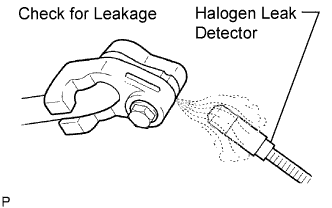
Using a halogen leak detector, check the refrigerant line for leakage.
-
If a gas leak is not detected on the drain hose, remove the blower motor control (blower resistor) from the cooling unit. Insert the halogen leak detector sensor into the unit and perform the test.
-
Disconnect the connector and wait for approximately 20 minutes. Bring the halogen leak detector close to the pressure switch and perform the test.
-
- Click here
INSTALL FRONT BUMPER COVER
-
for Standard:
-
w/ Winch:
-