REAR EVAPORATOR TEMPERATURE SENSOR (w/ Heater) REASSEMBLY

-
INSTALL WIRING AIR CONDITIONING HARNESS SUB-ASSEMBLY
-
INSTALL REAR EVAPORATOR TEMPERATURE SENSOR
-
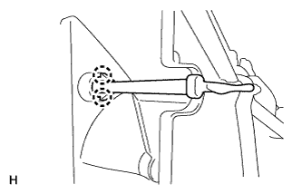
Attach the 2 claws to install the sensor.
-
-
INSTALL EVAPORATOR SUB-ASSEMBLY
-
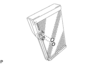
Sufficiently apply compressor oil to 2 new O-rings and the fitting surface of the hose joint.
Compressor oil ND-OIL 8 or equivalent -
Install the 2 O-rings to the evaporator.
-
Install the evaporator.
-
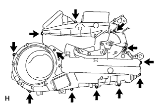
Install the rear cooling unit case LH with the 12 screws.
-
-
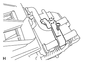
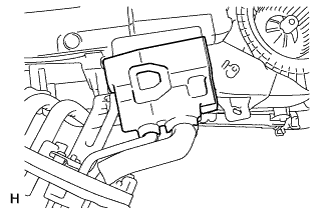
INSTALL BLOWER MOTOR CONTROLLER
-
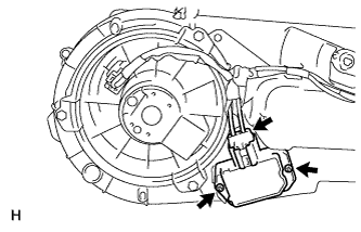
Install the blower motor controller with the 2 screws.
-
Connect the connector.
-
-
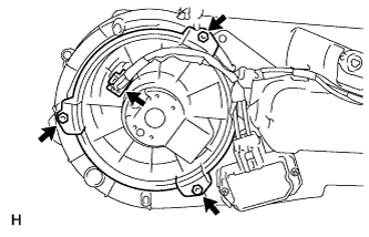
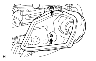
INSTALL REAR BLOWER MOTOR
-
Install the blower motor with the 3 screws.
-
Connect the connector.
-
-
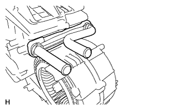
INSTALL HEATER RADIATOR UNIT SUB-ASSEMBLY
-
Install the radiator unit to the rear cooling unit.
-
Install the heater clamp with the screw and attach the claw.
-
-
INSTALL REAR COOLING UNIT EXPANSION VALVE
-
Using a 4 mm hexagon wrench, install the expansion valve with the 2 hexagon bolts.
- Torque:
- 3.5 N*m { 36 kgf*cm, 31 in.*lbf }
-
Attach the clamp.
-
Connect the connector.
-
-
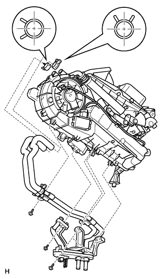
INSTALL AIR CONDITIONER ACCESSORY ASSEMBLY
-
Sufficiently apply compressor oil to 2 new O-rings and the fitting surface of the hose joint.
Compressor oil ND-OIL 8 or equivalent -
Install the 2 O-rings to the air conditioner accessory assembly.
-
Install the air conditioner accessory assembly.
-
Using pliers, grip the claws of the clips and slide the 2 clips.
-
Install the bolt and 4 screws.
- Torque:
- 5.4 N*m { 55 kgf*cm, 48 in.*lbf }
-
Install new packing as shown in the illustration.
-
-
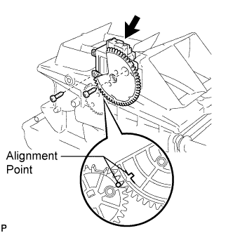
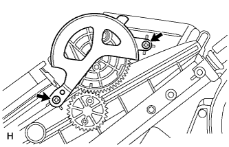
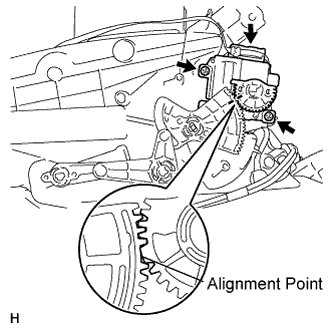
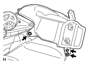
INSTALL REAR MODE DAMPER SERVO SUB-ASSEMBLY
-
Align the damper servo as shown in the illustration, and install it with the 2 screws.
-
Connect the connector.
-
Install the plate cover with the 2 screws.
-
-
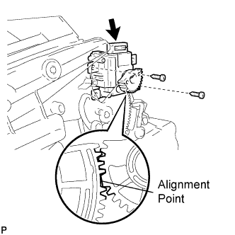
INSTALL NO. 2 AIR MIX DAMPER SERVO SUB-ASSEMBLY
-
Align the damper servo as shown in the illustration, and install it with the 2 screws.
-
Connect the connector.
-
-
INSTALL REAR AIR MIX DAMPER SERVO SUB-ASSEMBLY
-
Align the damper servo as shown in the illustration, and install it with the 2 screws.
-
Connect the connector.
-
-
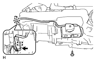
INSTALL DRAIN COOLER HOSE
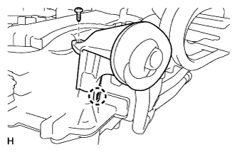
-
Attach the claw to install the drain hose.
-
Install the screw.
-
-
INSTALL REAR SIDE NO. 3 AIR DUCT
-
Install the duct with the 2 screws.
- Torque:
- 5.4 N*m { 55 kgf*cm, 48 in.*lbf }
-
-
INSTALL REAR SIDE NO. 2 AIR DUCT
-
Install the duct with the 3 screws.
- Torque:
- 5.4 N*m { 55 kgf*cm, 48 in.*lbf }
-