PARKING BRAKE SYSTEM ADJUSTMENT

-
INSPECT PARKING BRAKE LEVER TRAVEL
-
Fully pull the parking brake lever to engage the parking brake.
-
Release the lever to disengage the parking brake.
-
Slowly pull the parking brake lever all the way, and count the number of clicks.
Standard Parking Brake Lever Travel when Pulled with a Force of 200 N (20 kgf, 45 lbf) 5 to 7 clicks If the parking brake lever travel is not as specified, adjust the parking brake shoe clearance and parking brake lever travel.
-
-
REMOVE REAR WHEEL
-
REMOVE UPPER CONSOLE COVER (w/o Console Box Lid)
-
REMOVE CONSOLE CUP HOLDER BOX SUB-ASSEMBLY (w/ Cool Box)
-
REMOVE CONSOLE CUP HOLDER BOX SUB-ASSEMBLY (w/o Cool Box)
-
ADJUST PARKING BRAKE LEVER TRAVEL
-
Completely release the parking brake lever.
-
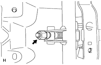
Loosen the adjusting nut to completely release the parking brake cable.
-
Temporarily install the hub nuts.
-
Remove the hole plug.
-
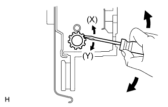
Insert an adjustment tool into the adjustment hole of the disc. Rotate the adjustment wheel in the "X" direction until the shoes are locked. Then rotate the adjustment wheel in the "Y" direction 8 notches.
-
Check that the disc can be rotated lightly. If not, rotate the adjustment wheel in the "Y" direction and check again.
-
Install the hole plug.
-
Remove the hub nuts.
-
Turn the adjusting nut until the parking brake lever travel becomes correct.
Standard Parking Brake Lever Travel when Pulled with a Force of 200 N (20 kgf, 45 lbf) 5 to 7 clicks -
Operate the parking brake lever 3 to 4 times, and check the parking brake lever travel.
Standard Parking Brake Lever Travel when Pulled with a Force of 200 N (20 kgf, 45 lbf) 5 to 7 clicks -
Check whether the parking brake drags or not.
-
When operating the parking brake lever, check that the brake warning light comes on.
Standard Condition The brake warning light always illuminates at the first click.
-
-
INSTALL UPPER CONSOLE COVER (w/o Console Box Lid)
-
INSTALL CONSOLE CUP HOLDER BOX SUB-ASSEMBLY (w/ Cool Box)
-
INSTALL CONSOLE CUP HOLDER BOX SUB-ASSEMBLY (w/o Cool Box)
-
INSTALL REAR WHEEL
- Torque:
- for Aluminum Wheel
- 131 N*m { 1336 kgf*cm, 97 ft.*lbf }
- for Steel Wheel
- 209 N*m { 2131 kgf*cm, 154 ft.*lbf }