- Click here
INSTALL VACUUM PUMP ASSEMBLY
-
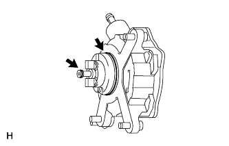
Apply engine oil to 2 new O-rings.
-
Install the 2 O-rings to the vacuum pump.
-
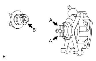
Install the vacuum pump so that the coupling teeth of the vacuum pump (labeled A) and the groove of the camshaft (labeled B) are aligned.
Note:Be careful not to damage the O-ring.
-
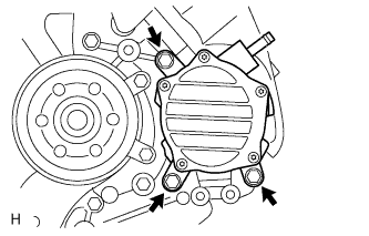
Install the vacuum pump with the 3 bolts.
21 N*m 214 kgf*cm 15 ft.*lbf Note:Confirm that the vacuum pump is not at an angle, and that there is no clearance between the fitting surfaces.
-
- Click here
CONNECT UNION TO CONNECTOR TUBE HOSE
-
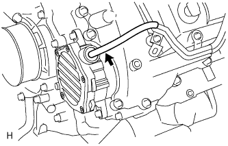
Connect the hose to the vacuum pump.
-
- Click here
INSTALL NO. 2 IDLER PULLEY BRACKET (w/ Viscous Heater)
-
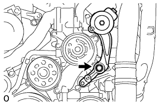
Temporarily install the No. 2 idler pulley bracket with the bolt.
-
Temporarily install the 2 bolts to the No. 2 idler pulley bracket bolt hole.
-
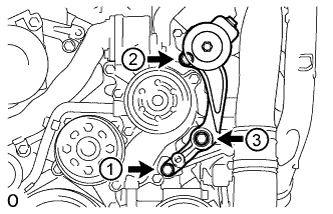
Uniformly tighten the 3 bolts of the No. 2 idler pulley bracket in the order shown in the illustration.
49 N*m 495 kgf*cm 36 ft.*lbf
-
- Click here
INSTALL NO. 2 IDLER PULLEY (w/ Viscous Heater)
-
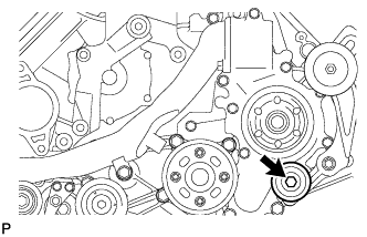
Install the collar, No. 2 idler pulley and cover with the bolt.
49 N*m 495 kgf*cm 36 ft.*lbf
-
- Click here
INSTALL V-RIBBED BELT (w/ Viscous Heater)
-
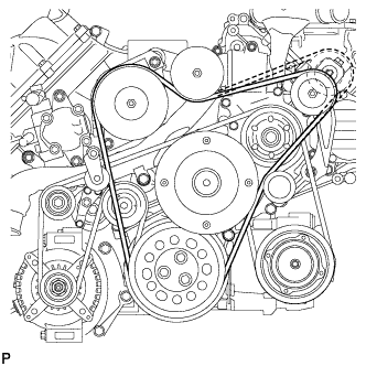
Install the V-ribbed belt as shown in the illustration.
-
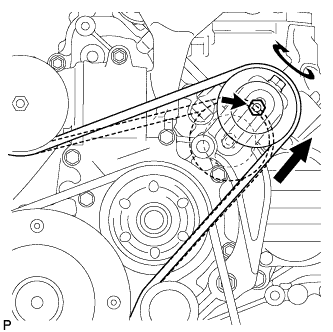
Temporarily install the lock nut, and turn the bolt clockwise.
-
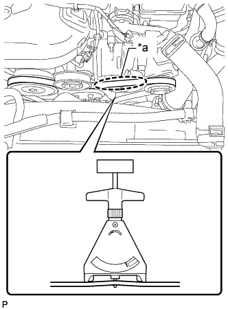
Using a belt tension gauge, inspect the belt tension.
Standard Belt Tension Item Condition Specified Condition New belt 5 to 35°C (41 to 95°F) 550 to 800 N (56 to 82 kgf, 123.6 to 179.8 lbf) Used belt 5 to 35°C (41 to 95°F) 300 to 500 N (31 to 51 kgf, 67.4 to 112.4 lbf) Table 1. Text in Illustration *a Measuring Point Tip:
-
When measuring the tension of a new belt, measure the tension immediately after installing it to the engine but before starting the engine.
-
A "new belt" is a belt which has been used for less than 5 minutes on a running engine.
-
A "used belt" is a belt which has been used on a running engine for 5 minutes or more.
-
After installing a new belt, run the engine for approximately 5 minutes and then recheck the tension.
-
-
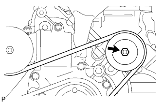
Tighten the nut.
40 N*m 408 kgf*cm 30 ft.*lbf -
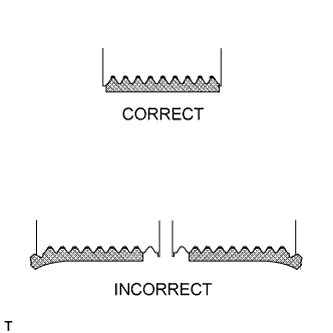
Check that the belt fits properly in the ribbed grooves.
Tip:Check with your hand to confirm that the belt has not slipped out of the groove on the bottom of the pulley.
If it has slipped out, replace the V-ribbed belt. Install a new V-ribbed belt.
-
- Click here
INSTALL NO. 2 AIR CLEANER PIPE SUB-ASSEMBLY
-
Connect the No. 2 air cleaner pipe to the No. 2 intake air connector pipe.
-
Connect the ventilation hose to the oil separator.
-
Install the pipe with the bolt.
21 N*m 214 kgf*cm 15 ft.*lbf -
Tighten the hose clamp.
6.3 N*m 64 kgf*cm 56 in.*lbf
-
- Click here
INSTALL NO. 4 AIR TUBE
-
Install the No. 4 air tube with the bolt.
21 N*m 214 kgf*cm 15 ft.*lbf Table 2. Text in Illustration *1 Paint Mark *a Top -
Tighten the hose clamp.
6.3 N*m 64 kgf*cm 56 in.*lbf Tip:Make sure the direction of the hose clamp is as shown in the illustration.
-
Install the suction hose with the bolt.
9.8 N*m 100 kgf*cm 87 in.*lbf
-
- Click here
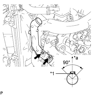
INSTALL NO. 2 AIR HOSE
-

Connect the No. 2 air hose with the hose clamp.
6.3 N*m 64 kgf*cm 56 in.*lbf Table 3. Text in Illustration *1 Protrusion *2 Paint Mark *a Top Tip:
-
Align the paint mark of the air hose with the protrusion and push on the air hose so that distance B is 0 to 3 mm (0 to 0.118 in.).
-
Position the clamp so that distance A is 2 to 6 mm (0.0787 to 0.236 in.).
-
Make sure the direction of the hose clamp is as shown in the illustration.
-
-
- Click here
INSTALL INTERCOOLER ASSEMBLY
-
Install the intercooler assembly (Click here).
-
- Click here
CHECK VACUUM PUMP OPERATION
-
Disconnect the union to connector tube hose from the vacuum pump.
-
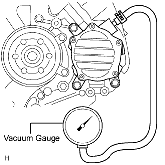
Connect a vacuum gauge to the vacuum pump.
-
Start the engine and warm it up for more than 2 minutes.
-
With the engine idling, measure the negative pressure of the vacuum pump.
Standard Pressure More than 86.7 kPa (650 mmHg, 25.6 in.Hg) Tip:It is necessary to replace the vacuum pump assembly every 200000 km (124000 miles).
-
Remove the vacuum gauge from the vacuum pump.
-
Connect the union to connector tube hose to the vacuum pump.
-