PARKING BRAKE CABLE INSTALLATION

Tech Tips
-
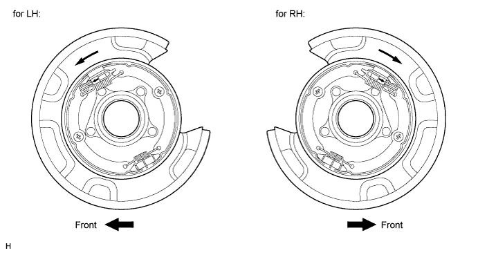
Use the same procedures for the LH side and RH side.
-
The procedures listed below are for the LH side.
-
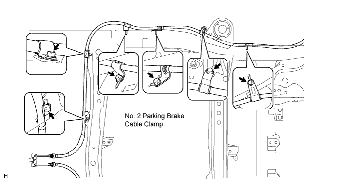
INSTALL NO. 2 PARKING BRAKE CABLE ASSEMBLY
-
Install the No. 2 parking brake cable clamp.
-
Install the No. 2 parking brake cable with the 6 bolts.
- Torque:
- 13 N*m { 127 kgf*cm, 9 ft.*lbf }
-
Install the fuel tank Click here.
-
Attach the claws of the No. 2 parking brake cable.
-
Connect the No. 2 parking brake cable to the No. 1 parking brake pull rod.
-
-
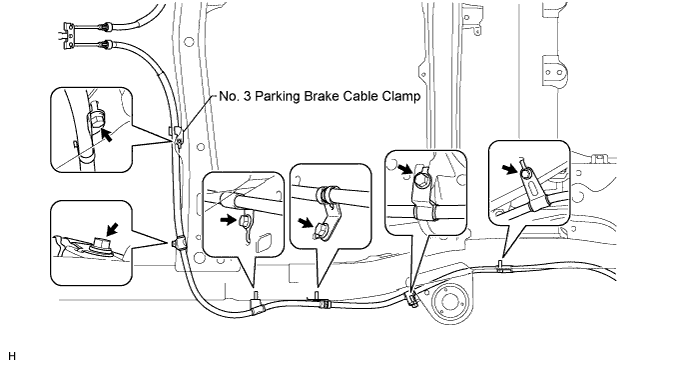
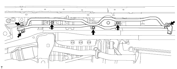
INSTALL NO. 3 PARKING BRAKE CABLE ASSEMBLY
-
Install the No. 3 parking brake cable clamp.
-
Install the No. 3 parking brake cable with the 6 bolts.
- Torque:
- 13 N*m { 127 kgf*cm, 9 ft.*lbf }
-
Attach the claws of the No. 3 parking brake cable.
-
Connect the No. 3 parking brake cable to the No. 1 parking brake pull rod.
-
-
CONNECT NO. 3 PARKING BRAKE CABLE ASSEMBLY
-
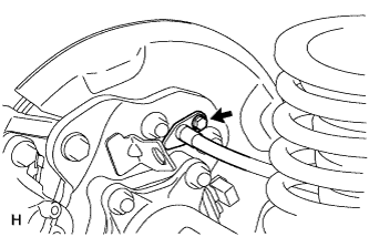
Connect the No. 3 parking brake cable with the bolt.
- Torque:
- 8.0 N*m { 82 kgf*cm, 71 in.*lbf }
-
-
INSTALL PARKING BRAKE SHOE LEVER LH
-
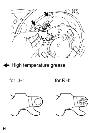
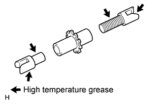
Apply high temperature grease to the parking brake anchor block.
-
Install the parking brake shoe lever to the No. 3 parking brake cable.
Note
Be carefully to distinguish between the parking brake shoe lever RH and LH.
-
-
INSTALL NO. 2 PARKING BRAKE SHOE ASSEMBLY LH
-
Apply high temperature grease to the areas of the backing plate that contact the shoe.
-
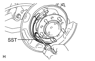
Using SST, install the No. 2 parking brake shoe with the shoe hold down spring pin, compression spring and shoe hold down spring cup.
- SST
- 09718-00011
-
-
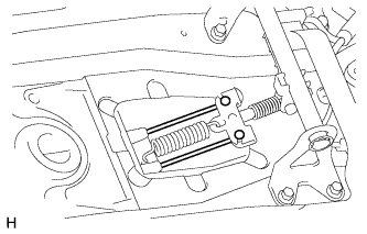
INSTALL NO. 1 PARKING BRAKE SHOE ASSEMBLY LH
-
Apply high temperature grease to the areas of the backing plate that contact the shoe.
-
Apply high temperature grease to the thread and all joining areas of the parking brake shoe adjuster screw set.
-
Set the No. 1 parking brake shoe and shoe adjuster screw set in place.
-
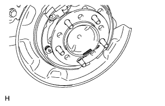
Connect the tension spring.
-
Using SST, install the shoe hold down spring pin, compression spring and shoe hold down spring cup.
- SST
- 09718-00011
-
-
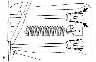
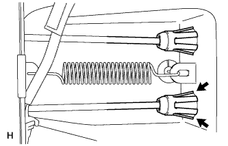
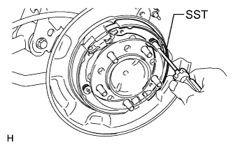
INSTALL PARKING BRAKE SHOE RETURN SPRING
-
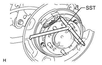
Using SST, install the shoe return spring.
- SST
- 09703-30011
-
-
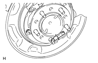
CHECK PARKING BRAKE INSTALLATION
-
Check that each part is installed properly.
-
-
INSTALL REAR DISC
-
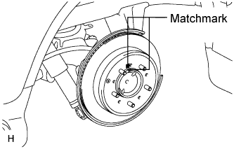
Align the matchmarks, and then install the rear disc.
Tech Tips
When replacing the rear disc with a new one, select the installation position where the rear disc has the minimum runout.
-
-
CONNECT REAR DISC BRAKE CYLINDER ASSEMBLY LH
-
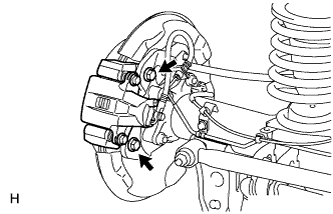
Connect the rear disc brake cylinder with 2 new bolts.
- Torque:
- 95 N*m { 969 kgf*cm, 70 ft.*lbf }
Note
-
Do not twist the brake hose.
-
Make sure that the bolts are free from damage and foreign matter.
-
Do not overtighten the bolts.
-
-
INSTALL REAR NO. 2 SUSPENSION CONTROL ACCUMULATOR BRACKET
-
Install the bracket to the shock absorber control valve with the bolt.
- Torque:
- 18 N*m { 184 kgf*cm, 13 ft.*lbf }
-
-
INSTALL HEIGHT CONTROL UNIT PROTECTOR PIPE
-
Install the protector pipe with the 6 bolts.
- Torque:
- 16 N*m { 163 kgf*cm, 12 ft.*lbf }
-
-
ADJUST PARKING BRAKE
-
INSTALL REAR WHEEL
- Torque:
- for Aluminum Wheel
- 131 N*m { 1336 kgf*cm, 97 ft.*lbf }
- for Steel Wheel
- 209 N*m { 2131 kgf*cm, 154 ft.*lbf }
-
INSTALL LOWER CONSOLE BOX (w/o Console Box Lid)
-
INSTALL COOLING BOX ASSEMBLY (w/ Cool Box)
-
INSTALL REAR CONSOLE BOX SUB-ASSEMBLY (w/o Cool Box)