| DTC Code | DTC Name |
|---|---|
| C146E | Open in ABS Solenoid Relay Circuit |
| C146F | Short in ABS Solenoid Relay Circuit |
DESCRIPTION
The solenoid relay is built into the master cylinder solenoid.
This relay supplies power to each solenoid. If the initial check is OK, after the ignition switch is turned to ON, the relay turns on.
| DTC Code | DTC Detection Condition | Trouble Area |
|---|---|---|
| C146E | Either condition is met:
|
|
| C146F | The following condition continues for at least 0.2 seconds.
|
WIRING DIAGRAM
Refer to DTCs C1225, C1226, C1227, C1228, C1468, C1469, C146A and C146B (Click here).
INSPECTION PROCEDURE
-
After replacing the master cylinder solenoid, perform zero point calibration and store the system information (Click here).
-
Inspect the fuses for circuits related to this system before performing the following inspection procedure.
PROCEDURE
- Click here
CHECK HARNESS AND CONNECTOR (+BS TERMINAL)
-
Turn the ignition switch off.
-
Disconnect the skid control ECU (master cylinder solenoid) connector.
-
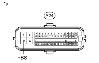
Measure the voltage according to the value(s) in the table below.
Standard Voltage Tester Connection Condition Specified Condition A24-31 (+BS) - Body ground Always 11 to 14 V Table 1. Text in Illustration *a Front view of wire harness connector
(to Skid Control ECU [Master Cylinder Solenoid])
- OKClick here
- NGClick here
-
- Click here
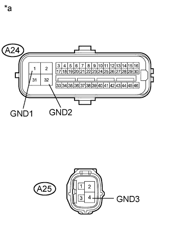
CHECK HARNESS AND CONNECTOR (GND1, GND2 AND GND3 TERMINAL)
-
Turn the ignition switch off.
-
Disconnect the skid control ECU (master cylinder solenoid) connectors.
-
Measure the resistance according to the value(s) in the table below.
Standard Resistance Tester Connection Condition Specified Condition A24-1 (GND1) - Body ground Always Below 1 Ω A24-32 (GND2) - Body ground Always Below 1 Ω A25-4 (GND3) - Body ground Always Below 1 Ω Table 2. Text in Illustration *a Front view of wire harness connector
(to Skid Control ECU [Master Cylinder Solenoid])
- OKClick here
- NGClick here
-
- Click here
RECONFIRM DTC
Tip:These codes are stored when a problem is detected in the master cylinder solenoid.
The solenoid relay is in the master cylinder solenoid.
Therefore, solenoid relay circuit inspections and relay unit inspections cannot be performed. Be sure to check if any DTC is output before replacing the master cylinder solenoid.
-
Clear the DTCs (Click here).
-
Turn the ignition switch off.
-
Drive the vehicle at a speed of approximately 32 km/h (20 mph) or more for 60 seconds or more.
-
Check if the same DTCs are output (Click here).
Tip:Reinstall the sensors, connectors, etc. and restore the previous vehicle conditions before rechecking for DTCs.
Table 3. Result Result Proceed to DTC is not output A DTC is output (for LHD) B DTC is output (for RHD) C
-
- Click here
REPLACE MASTER CYLINDER SOLENOIDClick here
- Click here
REPAIR OR REPLACE HARNESS OR CONNECTOR
- Click here
REPAIR OR REPLACE HARNESS OR CONNECTOR
- Click here
CHECK FOR INTERMITTENT PROBLEMSClick here
- Click here
REPLACE MASTER CYLINDER SOLENOIDClick here