VEHICLE STABILITY CONTROL SYSTEM Slip Indicator Light Remains ON
DESCRIPTION
The slip indicator light blinks during VSC, A-TRC, Crawl Control and hill-start assist control operation.
When the system fails, the slip indicator light comes on to warn the driver.
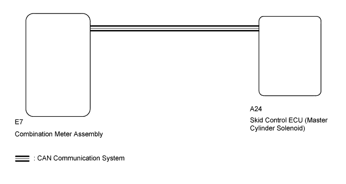
WIRING DIAGRAM
INSPECTION PROCEDURE
Note
After replacing the master cylinder solenoid, perform zero point calibration and store the system information Click here.
PROCEDURE
-
CHECK DTC
-
Check for DTCs Click here.
Result Result Proceed to DTC is not output A DTC is output B
B 
REPAIR CIRCUITS INDICATED BY OUTPUT DTC Click here
A 
-
-
INSPECT IF SKID CONTROL ECU CONNECTOR IS SECURELY CONNECTED
-
Check the skid control ECU (master cylinder solenoid) connector connection.
OK The connector is securely connected.
NG
CONNECT CONNECTOR TO ECU CORRECTLY
OK
-
-
INSPECT BATTERY
-
Check the battery voltage.
Standard voltage 11 to 14 V Result Result Proceed to OK A NG (for 1VD-FTV) B NG (for 1UR-FE) C NG (for 3UR-FE) D
B
GO TO CHARGING SYSTEM (ON-VEHICLE INSPECTION) Click here
C
GO TO CHARGING SYSTEM (ON-VEHICLE INSPECTION) Click here
D
GO TO CHARGING SYSTEM (ON-VEHICLE INSPECTION) Click here
A
-
-
CHECK CAN COMMUNICATION LINE
-
Turn the ignition switch off.
-
Connect the GTS to the DLC3.
-
Turn the ignition switch to ON and the GTS on.
-
Select "CAN Bus Check" from the System Selection Menu screen, and follow the prompts on the screen to inspect the CAN Bus.
OK "CAN Bus Check" indicates no malfunctions in CAN communication. Result Result Proceed to OK A NG (for LHD) B NG (for RHD) C
B
GO TO CAN COMMUNICATION SYSTEM (HOW TO PROCEED WITH TROUBLESHOOTING) Click here
C
GO TO CAN COMMUNICATION SYSTEM (HOW TO PROCEED WITH TROUBLESHOOTING) Click here
A
-
-
CHECK DTC (CAN COMMUNICATION SYSTEM)
-
Turn the ignition switch off.
-
Connect the GTS to the DLC3.
-
Turn the ignition switch to ON and the GTS on.
-
Check for DTCs (for LHD: Click here, for RHD: Click here.
Result Result Proceed to CAN system DTC is not output A CAN system DTC is output (for LHD) B CAN system DTC is output (for RHD) C
B
GO TO CAN COMMUNICATION SYSTEM (HOW TO PROCEED WITH TROUBLESHOOTING) Click here
C
GO TO CAN COMMUNICATION SYSTEM (HOW TO PROCEED WITH TROUBLESHOOTING) Click here
A
-
-
PERFORM ACTIVE TEST USING GTS (SLIP INDICATOR LIGHT)
-
Turn the ignition switch off.
-
Connect the GTS to the DLC3.
-
Turn the ignition switch to ON.
-
Turn the GTS on.
-
Enter the following menus: Chassis / ABS/VSC/TRC / Active Test.
ABS/VSC/TRC Tester Display Test Part Control Range Diagnostic Note Slip Indicator Light Slip indicator light Indicator light ON/OFF Observe the combination meter. -
When performing the Slip Indicator Light Active Test, check Slip Indicator Light in the Data List.
ABS/VSC/TRAC Tester Display Measurement Item/Range Normal Condition Diagnostic Note Slip Indicator Light Slip indicator light/ ON or OFF ON: Indicator light on
OFF: Indicator light off
- Result Result Proceed to Data List Display Data List Display when Performing Active Test ON/OFF Operation ON Changes between ON and OFF A Does not change between ON and OFF (for LHD) B Does not change between ON and OFF (for RHD) C OFF Changes between ON and OFF A Does not change between ON and OFF (for LHD) B Does not change between ON and OFF (for RHD) C
B
REPLACE MASTER CYLINDER SOLENOID Click here
C
REPLACE MASTER CYLINDER SOLENOID Click here
A 
GO TO METER / GAUGE SYSTEM (HOW TO PROCEED WITH TROUBLESHOOTING) Click here
-