DESCRIPTION
The skid control ECU (master cylinder solenoid) receives signals from the yaw rate sensor assembly via the CAN communication system.
The yaw rate sensor assembly has a built-in acceleration sensor and detects the vehicle's condition using 2 circuits (GL1, GL2).
If there is trouble in the bus lines between the yaw rate sensor assembly and the CAN communication system, DTCs U0123 (malfunction in CAN communication with the yaw rate sensor) and U0124 (malfunction in CAN communication with the acceleration sensor) are stored.
These DTCs are also stored when calibration has not been completed.
| DTC Code | DTC Detection Condition | Trouble Area |
|---|---|---|
| C1381 | At a vehicle speed of more than 3 km/h (2 mph), the acceleration sensor power source malfunction signal is received for 10 seconds or more. |
|
INSPECTION PROCEDURE
-
After replacing the yaw rate sensor assembly, perform calibration (Click here).
-
Inspect the fuses for circuits related to this system before performing the following inspection procedure.
PROCEDURE
- Click here
CHECK DTC (CAN COMMUNICATION SYSTEM)
-
Check for DTCs (Click here).
Table 1. Result Result Proceed to CAN DTC is not output A CAN DTC is output (for LHD) B CAN DTC is output (for RHD) C
-
- Click here
CHECK HARNESS AND CONNECTOR (IG/+B TERMINAL)
-
Turn the ignition switch off.
-
Disconnect the yaw rate sensor assembly connector.
-
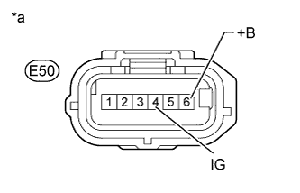
Measure the voltage according to the value(s) in the table below.
Standard Voltage Tester Connection Condition Specified Condition E50-4 (IG) - Body ground Ignition switch ON 11 to 14 V E50-6 (+B) - Body ground Always 11 to 14 V Table 2. Text in Illustration *a Front view of wire harness connector
(to Yaw Rate Sensor Assembly)
- OKClick here
- NGClick here
-
- Click here
CHECK HARNESS AND CONNECTOR (GND TERMINAL)
-
Turn the ignition switch off.
-
Disconnect the yaw rate sensor assembly connector.
-
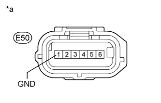
Measure the resistance according to the value(s) in the table below.
Standard Resistance Tester Connection Condition Specified Condition E50-1 (GND) - Body ground Always Below 1 Ω Table 3. Text in Illustration *a Front view of wire harness connector
(to Yaw Rate Sensor Assembly)
- OKClick here
- NGClick here
-
- Click here
RECONFIRM DTC
-
Reconnect the yaw rate sensor assembly connector.
-
Clear the DTCs (Click here).
-
Turn the ignition switch off.
-
Start the engine.
-
Perform a road test.
-
Check if the same DTC is output (Click here).
Table 4. Result Result Proceed to DTC C1381 is not output A DTC C1381 is output B
-
- Click here
CHECK FOR INTERMITTENT PROBLEMSClick here
- Click here
REPAIR OR REPLACE HARNESS OR CONNECTOR
- Click here
REPAIR OR REPLACE HARNESS OR CONNECTOR
- Click here
REPLACE YAW RATE SENSOR ASSEMBLYClick here
- Click here
GO TO CAN COMMUNICATION SYSTEM (HOW TO PROCEED WITH TROUBLESHOOTING)Click here
- Click here
GO TO CAN COMMUNICATION SYSTEM (HOW TO PROCEED WITH TROUBLESHOOTING)Click here