| DTC Code | DTC Name |
|---|---|
| C1422 | Master Cylinder Pressure Sensor Zero Point High Malfunction |
DESCRIPTION
Refer to DTCs C1421, C1423 and C1424 (Click here).
| DTC Code | DTC Detection Condition | Trouble Area |
|---|---|---|
| C1422 | When the stop light switch is off, the PM/C1 terminal voltage is 0.86 V or higher for 5 seconds or more. |
|
INSPECTION PROCEDURE
-
After replacing the master cylinder solenoid, perform zero point calibration (Click here).
-
Inspect the fuses for circuits related to this system before performing the following inspection procedure.
PROCEDURE
- Click here
READ VALUE USING GTS (STOP LIGHT SW)
-
Turn the ignition switch off.
-
Connect the GTS to the DLC3.
-
Turn the ignition switch to ON.
-
Turn the GTS on.
-
Enter the following menus: Chassis / ABS/VSC/TRC / Data List.
Table 1. ABS/VSC/TRC Tester Display Measurement Item/Range Normal Condition Diagnostic Note Stop Light SW Stop light switch / ON or OFF ON: Brake pedal depressed
OFF: Brake pedal released
- -
Check that the stop light switch condition observed on the GTS changes according to brake pedal operation.
OK The GTS displays ON and OFF according to brake pedal operation.
- OKClick here
- NGClick here
-
- Click here
CHECK BRAKE PEDAL AND STOP LIGHT SWITCH INSTALLATION
-
Turn the ignition switch off.
-
Check the brake pedal height and stop light switch installation (for LHD:Click here, for RHD:Click here).
OK The brake pedal height and stop light switch installation are normal.
- OKClick here
- NGClick here
-
- Click here
RECONFIRM DTC
-
Clear the DTC (Click here).
-
Turn the ignition switch off.
-
Start the engine.
-
Drive the vehicle at a speed of 40 km/h (25 mph) or more and perform a braking test (decelerate the vehicle by depressing the brake pedal).
-
Check if the same DTC is output (Click here).
Table 2. Result Result Proceed to DTC is not output A DTC is output (for LHD) B DTC is output (for RHD) C
-
- Click here
CHECK HARNESS AND CONNECTOR (STOP LIGHT SWITCH POWER SOURCE TERMINAL)
-
Make sure that there is no looseness in the locking part and connecting part of the connectors.
-
Disconnect the stop light switch assembly connector.
-
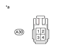
Measure the voltage according to the value(s) in the table below.
Standard Voltage Tester Connection Condition Specified Condition A30-2 - Body ground Always 11 to 14 V Table 3. Text in Illustration *a Front view of wire harness connector
(to Stop Light Switch Assembly)
- OKClick here
- NGClick here
-
- Click here
INSPECT STOP LIGHT SWITCH
-
Remove the stop light switch assembly (Click here).
-
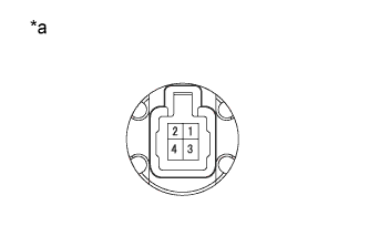
Measure the resistance according to the value(s) in the table below.
Standard Resistance Tester Connection Condition Specified Condition 1 - 2 Switch pin not pushed in Below 1 Ω Switch pin pushed in 10 kΩ or higher Table 4. Text in Illustration *a Component without harness connected
(Stop Light Switch Assembly)
- OKClick here
- NGClick here
-
- Click here
CHECK HARNESS AND CONNECTOR (STP TERMINAL)
-
Turn the ignition switch off.
-
Disconnect the skid control ECU (master cylinder solenoid) connector.
-
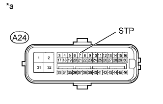
Measure the voltage according to the value(s) in the table below.
Standard Voltage Tester Connection Switch Condition Specified Condition A24-7 (STP) - Body ground Brake pedal depressed 8 to 14 V Brake pedal released Below 1.5 V Table 5. Text in Illustration *a Front view of wire harness connector
(to Skid Control ECU [Master Cylinder Solenoid])
Table 6. Result Result Proceed to NG A OK (for LHD) B OK (for RHD) C
-
- Click here
CHECK FOR INTERMITTENT PROBLEMSClick here
- Click here
REPLACE MASTER CYLINDER SOLENOIDClick here
- Click here
ADJUST BRAKE PEDAL OR STOP LIGHT SWITCH
- Click here
REPAIR OR REPLACE HARNESS OR CONNECTOR
- Click here
REPLACE STOP LIGHT SWITCH ASSEMBLYClick here
- Click here
REPLACE MASTER CYLINDER SOLENOIDClick here