DESCRIPTION
The motor relay (semiconductor relay) is built into the master cylinder solenoid and drives the pump motor based on a signal from the skid control ECU (master cylinder solenoid).
| DTC Code | DTC Detection Condition | Trouble Area |
|---|---|---|
| C1253 | There is a motor system circuit (motor input circuit) malfunction. |
|
INSPECTION PROCEDURE
-
After replacing the master cylinder solenoid, perform zero point calibration (Click here).
-
Inspect the fuses for circuits related to this system before performing the following inspection procedure.
PROCEDURE
- Click here
PERFORM ACTIVE TEST USING GTS (MOTOR RELAY)
-
Turn the ignition switch off.
-
Connect the GTS to the DLC3.
-
Turn the ignition switch to ON.
-
Turn the GTS on.
-
Start the engine.
-
Enter the following menus: Chassis / ABS/VSC/TRC / Active Test.
Table 1. ABS/VSC/TRC Tester Display Test Part Control Range Diagnostic Note Motor Relay Motor relay Relay ON/OFF An operating sound of the motor can be heard. -
Check the operating sound of the motor individually when operating it with the GTS.
OK An operating sound of the motor can be heard.
- OKClick here
- NGClick here
-
- Click here
RECONFIRM DTC
-
Clear the DTCs (Click here).
-
Turn the ignition switch off.
-
Depress the brake pedal more than 40 times.
-
Turn the ignition switch to ON.
-
Wait until the pump motor stops.
-
Depress the brake pedal several times until the pump motor turns on. (Procedure A)
-
Wait until the pump stops. (Procedure B)
-
Repeat the above steps (procedure A and B) 3 more times.
-
Check if the same DTC is output (Click here).
Tip:Reinstall the sensors, connectors, etc. and restore the previous vehicle conditions before rechecking for DTCs.
Table 2. Result Result Proceed to DTC is not output A DTC is output (for LHD) B DTC is output (for RHD) C
-
- Click here
CHECK HARNESS AND CONNECTOR (+BM1/+BM2 TERMINAL)
-
Turn the ignition switch off.
-
Disconnect the skid control ECU (master cylinder solenoid) connectors.
-
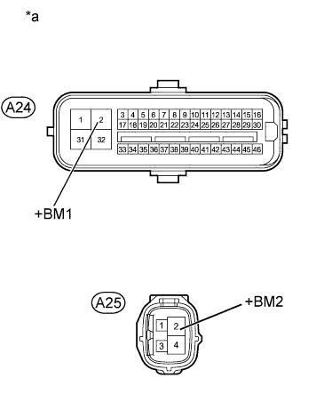
Measure the voltage according to the value(s) in the table below.
Standard Voltage Tester Connection Condition Specified Condition A24-2 (+BM1) - Body ground Always 11 to 14 V A25-2 (+BM2) - Body ground Always 11 to 14 V Table 3. Text in Illustration *a Front view of wire harness connector
(to Skid Control ECU [Master Cylinder Solenoid])
- OKClick here
- NGClick here
-
- Click here
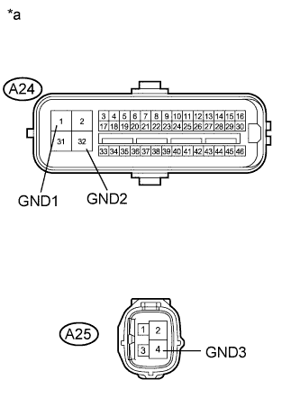
CHECK HARNESS AND CONNECTOR (GND1, GND2 AND GND3 TERMINAL)
-
Turn the ignition switch off.
-
Disconnect the skid control ECU (master cylinder solenoid) connectors.
-
Measure the resistance according to the value(s) in the table below.
Standard Resistance Tester Connection Condition Specified Condition A24-1 (GND1) - Body ground Always Below 1 Ω A24-32 (GND2) - Body ground Always Below 1 Ω A25-4 (GND3) - Body ground Always Below 1 Ω Table 4. Text in Illustration *a Front view of wire harness connector
(to Skid Control ECU [Master Cylinder Solenoid])
- OKClick here
- NGClick here
-
- Click here
RECONFIRM DTC
-
Clear the DTCs (Click here).
-
Turn the ignition switch off.
-
Depress the brake pedal more than 40 times.
-
Turn the ignition switch to ON.
-
Wait until the pump motor stops.
-
Depress the brake pedal several times until the pump motor turns on. (Procedure A)
-
Wait until the pump stops. (Procedure B)
-
Repeat the above steps (procedure A and B) 3 more times.
-
Check if the same DTC is output (Click here).
Tip:Reinstall the sensors, connectors, etc. and restore the previous vehicle conditions before rechecking for DTCs.
Table 5. Result Result Proceed to DTC is not output A DTC is output (for LHD) B DTC is output (for RHD) C
-
- Click here
REPLACE MASTER CYLINDER SOLENOIDClick here
- Click here
REPAIR OR REPLACE HARNESS OR CONNECTOR
- Click here
REPAIR OR REPLACE HARNESS OR CONNECTOR
- Click here
CHECK FOR INTERMITTENT PROBLEMSClick here
- Click here
REPLACE MASTER CYLINDER SOLENOIDClick here