ANTI-LOCK BRAKE SYSTEM, Diagnostic DTC:C1243, C1245, C1279, C1381, C1418

| DTC Code | DTC Name |
|---|---|
| C1243 | Acceleration Sensor Stuck Malfunction |
| C1245 | Acceleration Sensor Output Malfunction |
| C1279 | Acceleration Sensor Output Voltage Malfunction (Test Mode DTC) |
| C1381 | Acceleration Sensor Power Supply Voltage Malfunction |
| C1418 | Open or Short in Acceleration Sensor Circuit |
DESCRIPTION
The skid control ECU (master cylinder solenoid) receives signals from the deceleration sensor. If the sensor functions abnormally, the ABS warning light turns on.
| DTC Code | DTC Detection Condition | Trouble Area |
|---|---|---|
| C1243 | The following condition repeats 16 times.
|
|
| C1245 | The following condition continues for at least 60 seconds.
|
|
| C1381 | At a vehicle speed of more than 3 km/h (2 mph), the deceleration sensor power source malfunction signal is received for 10 seconds or more. | |
| C1418 | One of the following conditions is met when the voltage at terminal IG1 is 9.5 V or higher:
|
|
| C1279 | Stored during test mode. |
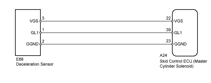
WIRING DIAGRAM
INSPECTION PROCEDURE
Note
After replacing the deceleration sensor, perform zero point calibration Click here.
PROCEDURE
-
CHECK DECELERATION SENSOR INSTALLATION
-
Check that the deceleration sensor is installed properly.
Result Result Proceed to The sensor is tightened to the specified torque.
The sensor is not tilted.
A The sensor is not tightened to the specified torque.
Or the sensor is tilted.
B
B 
INSTALL DECELERATION SENSOR CORRECTLY Click here
A 
-
-
READ VALUE USING GTS (DECELERATION SENSOR)
-
Turn the ignition switch off.
-
Connect the GTS to the DLC3.
-
Start the engine.
-
Turn the GTS on.
-
Enter the following menus: Chassis / ABS/VSC/TRC / Data List.
ABS/VSC/TRC Tester Display Measurement Item/Range Normal Condition Diagnostic Note Deceleration Sensor Deceleration sensor reading / min.: -18.525 m/s2, max.: 18.387 m/s2
Approximately -1.28 to 1.27 m/s2while stationary
The reading changes when the vehicle is bounced. -
Check the Data List for proper functioning of the deceleration sensor.
OK Deceleration value changes.
NG 
INSPECT DECELERATION SENSOR Click here
OK
-
-
CHECK DTC
-
Install the deceleration sensor to the vehicle.
-
Clear the DTCs Click here.
-
Turn the ignition switch off.
-
Drive the vehicle at 6 km/h (4 mph) or more.
-
Check if the same DTCs are output Click here.
Result Result Proceed to DTC is not output A DTC is output (for LHD) B DTC is output (for RHD) C
B
REPLACE MASTER CYLINDER SOLENOID Click here
C
REPLACE MASTER CYLINDER SOLENOID Click here
A 
CHECK FOR INTERMITTENT PROBLEMS Click here
-
-
INSPECT DECELERATION SENSOR
-
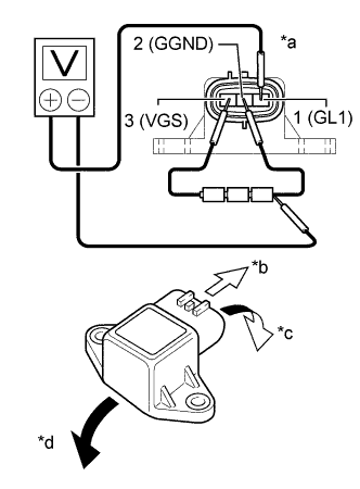
Text in Illustration *a Component without harness connected
(Deceleration Sensor)
*b Front *c Tilted forward *d Tilted rearward Remove the deceleration sensor Click here.
-
Connect 3 dry cell batteries of 1.5 V in series.
Note
Do not apply 6 V or more to terminals 3 (VGS) and 2 (GGND).
-
Check the output voltage of terminal 1 (GL1) when the sensor is tilted forward and rearward.
Standard Voltage Tester Connection Condition Specified Condition 1 (GL1) - Battery negative (-) lead Horizontal Approximately 2.5 V Tilted forward Approximately 0.5 to 2.5 V Tilted rearward Approximately 2.5 to 4.5 V Tech Tips
-
If the sensor is tilted too much, it may output the wrong value.
-
If the voltage drops, the sensor should be replaced with a new one.
-
When replacing the sensor, it should not be placed upside down.
-
NG
REPLACE DECELERATION SENSOR Click here
OK
-
-
CHECK HARNESS AND CONNECTOR (SKID CONTROL ECU - DECELERATION SENSOR)
-
Disconnect the A24 skid control ECU (master cylinder solenoid) connector.
-
Disconnect the E88 deceleration sensor connector.
-
Measure the resistance according to the value(s) in the table below.
Standard Resistance Tester Connection Condition Specified Condition A24-39 (GL1) - E88-1 (GL1) Always Below 1 Ω A24-23 (GGND) - E88-2 (GGND) Always Below 1 Ω A24-22 (VGS) - E88-3 (VGS) Always Below 1 Ω E88-1 (GL1) - Body ground Always 10 kΩ or higher E88-2 (GGND) - Body ground Always 10 kΩ or higher E88-3 (VGS) - Body ground Always 10 kΩ or higher
NG
REPAIR OR REPLACE HARNESS OR CONNECTOR
OK
-
-
CHECK DTC
-
Install the deceleration sensor to the vehicle.
-
Clear the DTCs Click here.
-
Turn the ignition switch off.
-
Drive the vehicle at 6 km/h (4 mph) or more.
-
Check if the same DTCs are output Click here.
Result Result Proceed to DTC is not output A DTC is output (for LHD) B DTC is output (for RHD) C
B
REPLACE MASTER CYLINDER SOLENOID Click here
C
REPLACE MASTER CYLINDER SOLENOID Click here
A
CHECK FOR INTERMITTENT PROBLEMS Click here
-