REAR STABILIZER BAR (w/ KDSS) INSTALLATION

-
INSTALL REAR SUSPENSION CONTROL BLEEDER PLUG
-
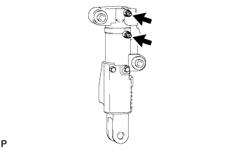
Install the 2 suspension control bleeder plugs to the rear stabilizer control cylinder.
- Torque:
- 8.3 N*m { 85 kgf*cm, 73 in.*lbf }
-
-
INSTALL REAR STABILIZER LINK ASSEMBLY
-
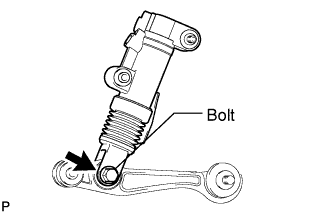
Install the rear stabilizer link with the bolt and nut.
- Torque:
- 208 N*m { 2121 kgf*cm, 153 ft.*lbf }
Note
Make sure the bolt is facing the correct direction.
-
-
INSTALL REAR NO. 2 STABILIZER LINK
-
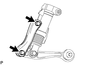
Install the No. 2 rear stabilizer link with the 2 bolts and 2 nuts.
- Torque:
- 97 N*m { 989 kgf*cm, 72 ft.*lbf }
Note
Make sure the bolts are facing the correct direction.
-
-
TEMPORARILY INSTALL REAR STABILIZER CONTROL CYLINDER
-
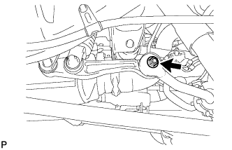
Temporarily install the rear stabilizer control cylinder to the frame with the bolt.
-
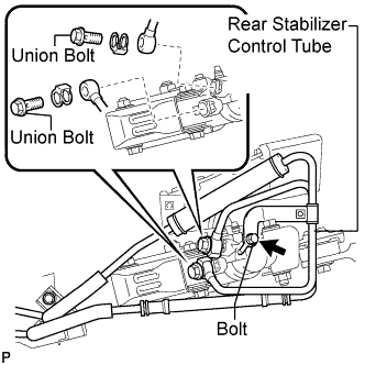
Install the rear stabilizer control tube and 2 new gaskets to the rear stabilizer control cylinder with the 2 union bolts.
- Torque:
- 69 N*m { 704 kgf*cm, 51 ft.*lbf }
-
Install the bolt.
- Torque:
- 29 N*m { 296 kgf*cm, 21 ft.*lbf }
-
-
INSTALL STABILIZER LINK SUB-ASSEMBLY
-
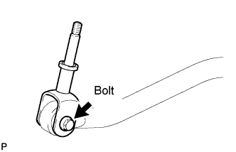
Install the stabilizer link to the stabilizer bar with the bolt and nut.
- Torque:
- 48 N*m { 489 kgf*cm, 35 ft.*lbf }
Note
Make sure the bolt is facing the correct direction.
-
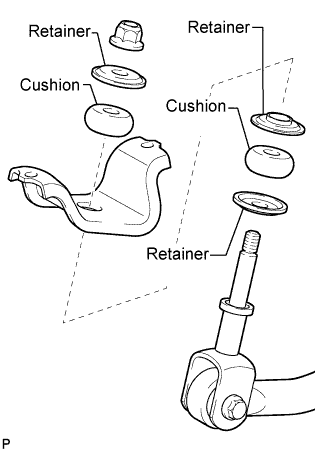
Make sure that all parts are facing as shown in the illustration and install the stabilizer end bracket, retainers and cushions with a new nut.
- Torque:
- 30 N*m { 306 kgf*cm, 22 ft.*lbf }
-
-
INSTALL REAR STABILIZER BAR SUB-ASSEMBLY
-
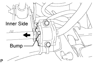
Install the 2 bushes to the outer side of the bush stoppers on the rear stabilizer bar as shown in the illustration.
Note
Install the stabilizer bush so that the bump is on the inner side of the vehicle.
-
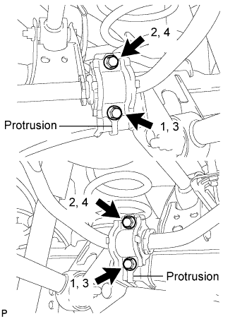
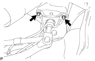
Install the 2 stabilizer bar brackets with the 4 bolts.
- Torque:
- 58 N*m { 591 kgf*cm, 43 ft.*lbf }
Note
-
Install the stabilizer bar bracket so that the protrusion is on the lower side.
-
Tighten the bolts in 4 steps, in the order shown in the illustration.
-
Install the stabilizer end bracket with the 2 bolts.
- Torque:
- 30 N*m { 306 kgf*cm, 22 ft.*lbf }
-
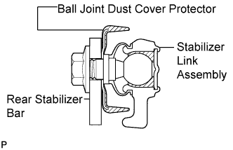
Install the stabilizer link assembly to the ball joint dust cover protector.
-
Install the stabilizer bar to the stabilizer link with the nut.
- Torque:
- 100 N*m { 1020 kgf*cm, 74 ft.*lbf }
Tech Tips
-
If the ball joint turns together with the nut, use a 6 mm hexagon wrench to hold the stud bolt.
-
If the rear stabilizer control cylinder extends and it is difficult to temporarily install the stabilizer link to the stabilizer bar, raise the stabilizer control arm with a jack and temporarily install the stabilizer link.
-
-
BLEED AIR FROM SUSPENSION FLUID
-
Bleed air from the suspension fluid Click here.
-
-
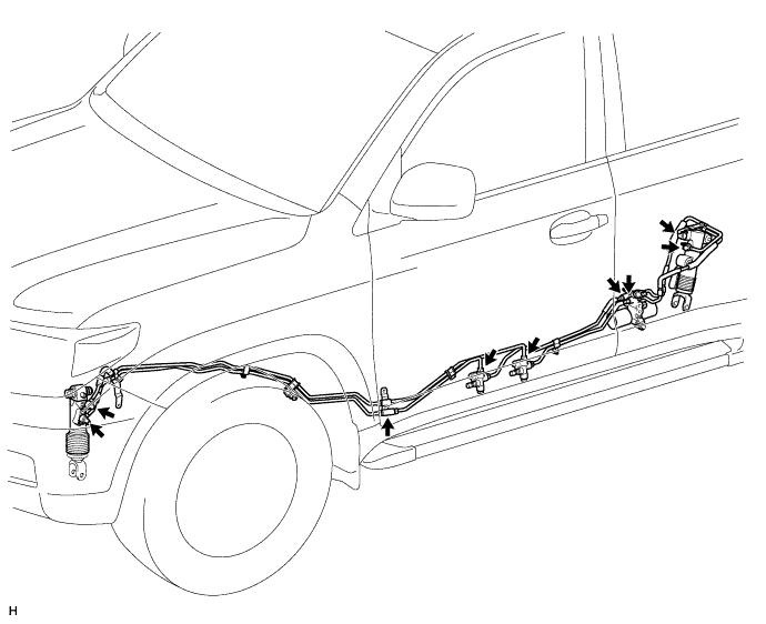
INSPECT FOR SUSPENSION FLUID LEAK
CAUTION:
Fluid is pumped into the system at a high pressure of approximately 3 MPa (30.6 kgf/cm2, 435 psi). If a fluid leak is discovered, immediately release the pressure and repair the fluid leak.
-
Perform a driving test.
-
Check for fluid leakage from the parts and connections.
-
-
INSTALL EXHAUST CENTER PIPE ASSEMBLY
-
for 1GR-FE:
Install the center exhaust pipe Click here.
-
for 1UR-FE:
Install the center exhaust pipe Click here.
-
for 3UR-FE:
Install the center exhaust pipe Click here.
-
for 1VD-FTV:
Install the center exhaust pipe Click here.
-
-
INSTALL TAILPIPE ASSEMBLY
-
for 1GR-FE:
Install the tailpipe Click here.
-
for 1UR-FE:
Install the tailpipe Click here.
-
for 3UR-FE:
Install the tailpipe Click here.
-
for 1VD-FTV:
Install the tailpipe Click here.
-
-
STABILIZE SUSPENSION
-
Install the rear wheels.
- Torque:
- for aluminum wheel
- 131 N*m { 1336 kgf*cm, 97 ft.*lbf }
- for steel wheel
- 209 N*m { 2131 kgf*cm, 154 ft.*lbf }
-
Lower the vehicle.
-
Press down on the vehicle several times to stabilize the suspension.
-
-
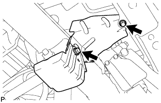
TIGHTEN REAR STABILIZER CONTROL CYLINDER
-
Tighten the bolt.
- Torque:
- 90 N*m { 918 kgf*cm, 66 ft.*lbf }
Note
Perform this procedure with all 4 wheels on the ground.
-
-
INSTALL REAR STABILIZER CONTROL TUBE INSULATOR
-
Install the rear stabilizer control tube insulator with the 2 bolts.
- Torque:
- 18 N*m { 184 kgf*cm, 13 ft.*lbf }
-
-
MEASURE VEHICLE HEIGHT
Note
-
Perform the inspection on a level surface.
-
Ensure that the wheels are on the ground and facing straight ahead.
-
Perform the inspection with the vehicle load completely on the suspension.
Tech Tips
-
Perform this step with the fuel tank full.
-
If there are any parts installed to the vehicle which place any unbalanced load on the left or right side of the vehicle, remove them.
-
Set the tire pressure to the specified value(s) Click here.
-
Bounce the vehicle to stabilize the suspension.
-
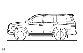
Measure the distance from the ground to the top of the bumper and calculate the difference in the vehicle height between left and right. Perform this procedure for both the front and rear wheels.
Height difference of left and right sides 15 mm (0.591 in.) or less Tech Tips
If not as specified, perform the vehicle tilt calibration.
-
-
CLOSE STABILIZER CONTROL WITH ACCUMULATOR HOUSING SHUTTER VALVE
Note
-
Perform the inspection on a level surface.
-
Ensure that the wheels are on the ground and facing straight ahead.
-
Perform the inspection with the vehicle load completely on the suspension.
Tech Tips
-
Perform this step with the fuel tank full.
-
If there are any parts installed to the vehicle which place any unbalanced load on the left or right side of the vehicle, remove them.
-
Using a 5 mm hexagon socket wrench, tighten the lower and upper chamber shutter valves of the stabilizer control with accumulator housing.
- Torque:
- 14 N*m { 143 kgf*cm, 10 ft.*lbf }
-
-
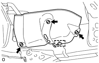
INSTALL STABILIZER CONTROL VALVE PROTECTOR
-
Install the valve protector with the 3 bolts.
- Torque:
- 18 N*m { 184 kgf*cm, 13 ft.*lbf }
-
Attach the clamp, and connect the connector to the valve protector.
-