FRONT LOWER SUSPENSION ARM REMOVAL

Tech Tips
-
Use the same procedures for the RH side and LH side.
-
The procedures listed below are for the LH side.
-
REMOVE STABILIZER CONTROL VALVE PROTECTOR (w/ KDSS)
-
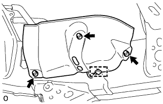
Detach the clamp, and disconnect the connector from the protector.
-
Remove the 3 bolts and protector.
-
-
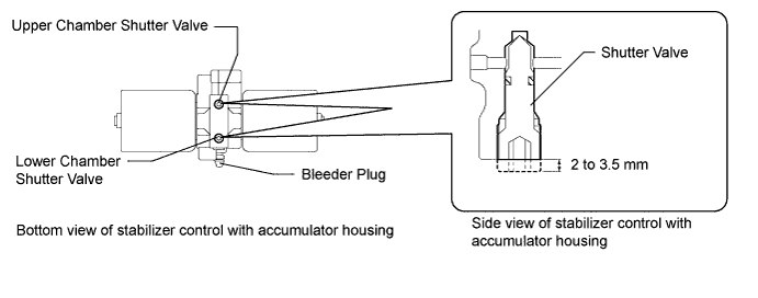
OPEN STABILIZER CONTROL WITH ACCUMULATOR HOUSING SHUTTER VALVE (w/ KDSS)
-
Using a 5 mm hexagon socket wrench, loosen the lower and upper chamber shutter valves of the stabilizer control with accumulator housing 2.0 to 3.5 turns.
Note
-
When loosening a shutter valve, make sure that the end protrudes 2 to 3.5 mm (0.0787 to 0.137 in.) from the surface of the block, and do not turn the shutter valve any further.
-
Do not remove the shutter valves.
-
-
-
REMOVE FRONT WHEEL
-
REMOVE FRONT FENDER SPLASH SHIELD SUB-ASSEMBLY LH
-
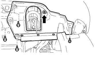
Remove the 3 bolts and screw.
-
Turn the clip indicated by the arrow in the illustration to remove the front fender splash shield sub-assembly LH.
-
-
REMOVE FRONT FENDER SPLASH SHIELD SUB-ASSEMBLY RH
-
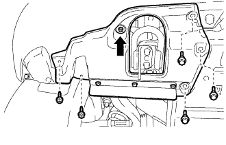
Remove the 3 bolts and 2 screws.
-
Turn the clip indicated by the arrow in the illustration to remove the front fender splash shield sub-assembly RH.
-
-
REMOVE NO. 1 ENGINE UNDER COVER SUB-ASSEMBLY
-
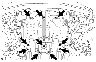
Remove the 10 bolts and No. 1 engine under cover sub-assembly.
-
-
LOOSEN FRONT NO. 1 STABILIZER BRACKET LH
-
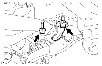
Loosen the 2 bolts of the front stabilizer brackets.
-
-
LOOSEN FRONT NO. 1 STABILIZER BRACKET RH
-
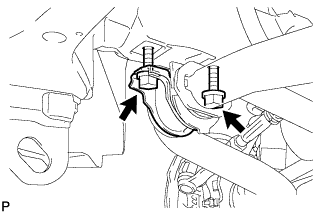
Loosen the 2 bolts of the front stabilizer brackets.
-
-
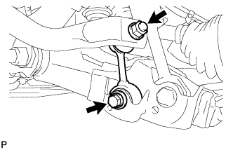
REMOVE FRONT STABILIZER LINK ASSEMBLY LH (w/ KDSS)
-
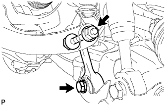
Remove the 2 bolts, nut and stabilizer link.
-
-
REMOVE FRONT STABILIZER LINK ASSEMBLY LH (w/o KDSS)
-
Remove the bolt, nut and stabilizer link.
-
-
REMOVE FRONT STABILIZER LINK ASSEMBLY RH
-
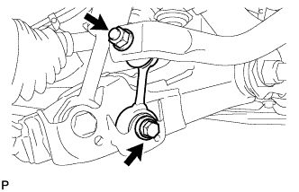
Remove the bolt, nut and stabilizer link.
Tech Tips
If the ball joint turns together with the nut, use a 6 mm hexagon wrench to hold the stud.
-
-
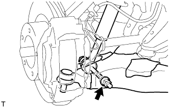
DISCONNECT FRONT SHOCK ABSORBER WITH COIL SPRING LH
-
Remove the nut and bolt, and disconnect the shock absorber from the lower side.
-
-
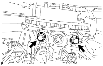
DISCONNECT FRONT LOWER BALL JOINT ATTACHMENT LH
-
Remove the 2 bolts and disconnect the attachment from the steering knuckle.
-
-
REMOVE FRONT NO. 1 SUSPENSION ARM LOWER SUB-ASSEMBLY LH
-
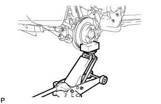
Support the front suspension LH with a jack.
-
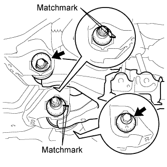
Place matchmarks on the No. 2 camber adjusting cam and No. 2 suspension toe adjusting plate.
-
Remove the nut, washer, No. 2 camber adjusting cam, camber adjusting cam assembly, bolt, toe adjusting cam, No. 2 suspension toe adjusting plate and front No. 1 suspension arm lower LH.
-
-
REMOVE FRONT LOWER BALL JOINT ATTACHMENT LH
-
Remove the cotter pin and nut.
-
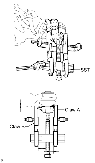
Using SST, remove the lower ball joint attachment.
- SST
- 09950-40011 ( 09951-04010, 09953-04020, 09954-04010, 09955-04031, 09958-04011, 09952-04010 )
- 09955-04090
Tech Tips
Claw A 09955-04090
Claw B 09955-04031
-